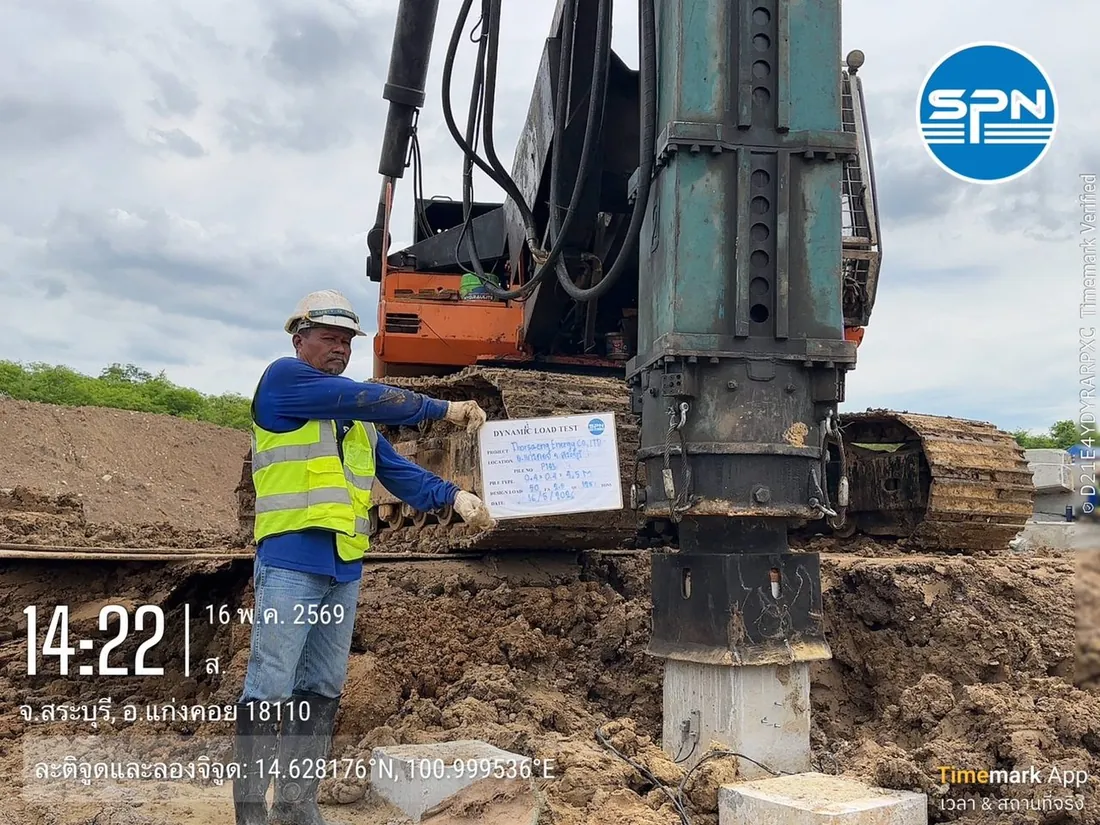
What is a pile test report, and how does it differ from a certificate?
A pile test report is a document that records the results of load capacity or integrity testing of piles actually installed on site, prepared and certified by a civil engineer to confirm that the piles perform as designed. The report is the engineering evidence used during construction and in submissions to the relevant authorities.
In practice, reports are usually split by test method, e.g. a Dynamic Load Test (PDA) report, a Static Load Test report and a Seismic Integrity Test report. All three share a similar core structure and differ in the details of the raw data and the standards referenced.
A certificate and a full report are not the same document. A certificate is usually a one-page summary of results with the engineer's signature, while the full report contains the raw data, graphs and analysis that make the results traceable. A common situation for project owners and contractors is receiving one "certificate" and assuming that is everything, so both should be requested together. The checklist below helps check completeness before accepting the work and before using it.
The figure below opens a full report out into two pages. Match the numbers 1–8 on the report pages against the checklist on the right. Red tags mark the items most often missing, as explained under each item, and the lower-left box compares a 1-page certificate with a full report.
What must a pile test report include? An 8-point checklist
A complete report has 8 main parts, from pile information to appendices, and can be used straight away as a checklist before accepting a report and before submitting it.
1. Project and pile information
- Project name, location and owner
- Number and location of each tested pile, referenced to the foundation plan
- Pile type (driven / bored / spun), cross-section size, length and installation date
- Design load of that pile
This information "ties" the report to the actual pile. Without the pile number or installation date, the report cannot be traced back. The installation date is also used to check whether the concrete was old enough at the time of testing (see the criteria in At what concrete age should piles be tested?)
2. Test method and reference standards
The report must state the test method and the standards used clearly, not just a vague "tested per international standards". It should give both the name of the standard and the edition used, because some standards have been revised or withdrawn.
← Scroll to see the full table →
| Test method | Reference standards used in Thailand | What the report answers |
|---|---|---|
| Dynamic Load Test (PDA) | DPT 1252-51 (same approach as ASTM D4945; current edition D4945-26) | Assessed load capacity |
| Static Load Test | DPT 1251 and ASTM D1143/D1143M-20e1 | Load capacity from actual loading |
| Seismic / Integrity Test | DPT 1551-51 | Integrity of the pile shaft |
ASTM withdrew D5882 (Low Strain Impact Integrity Testing) and D6760 (Crosshole Sonic Logging) in 2025 (with no replacement editions at present). For work in Thailand, the main reference standard is DPT 1551-51 of the Department of Public Works and Town & Country Planning, which remains in normal use, while CSL work now refers to the ACI PRC-228.2 guidance. If a report cites ASTM D5882 (withdrawn by ASTM in 2025) as its main standard, ask the author about the current status of the standard used (see the list of changed standards in Pile Testing Standards Update 2026)
3. Equipment and calibration information
The report should state the model and serial number (S/N) of the equipment used, such as the Pile Driving Analyzer, accelerometers and strain transducers, together with their calibration status, to confirm that the measured values are reliable. The serial numbers in the body of the report should match the calibration certificates in the appendix. This is the part cheap reports often leave out, even though reviewers usually ask to see it first.
4. Raw data and test result graphs
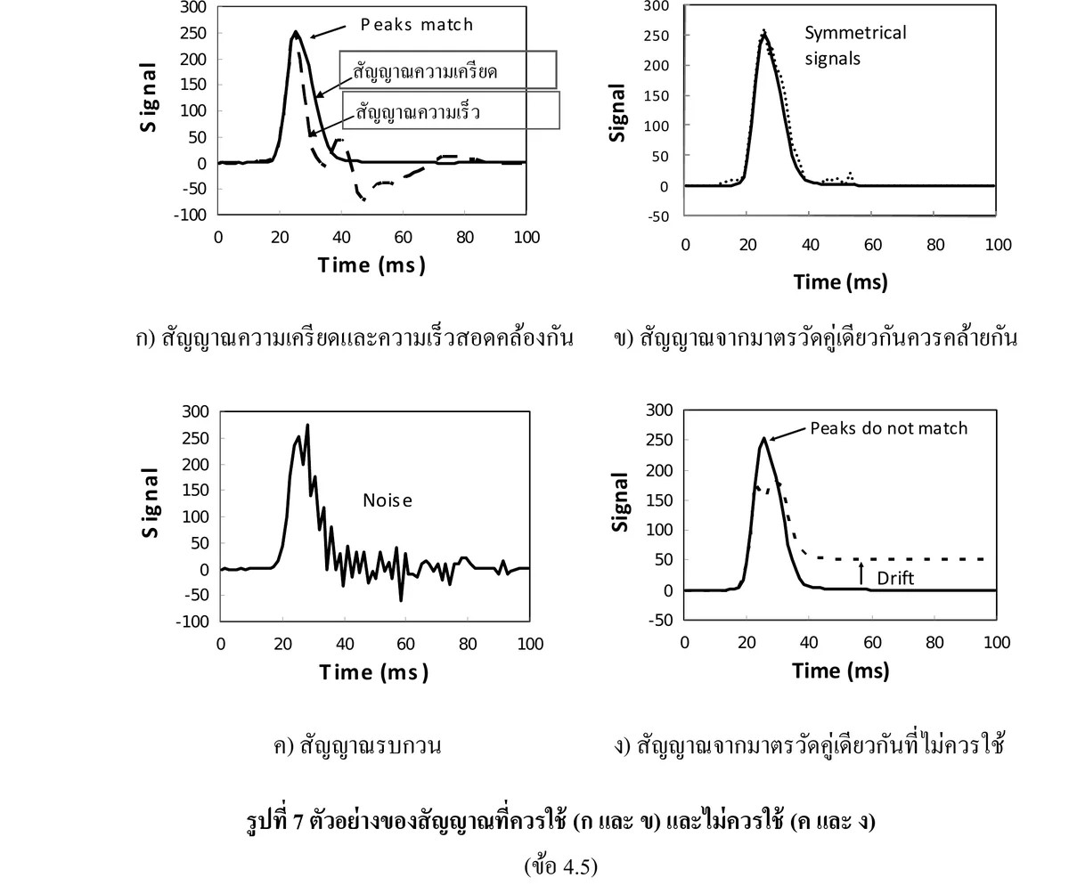
- PDA — force and velocity (Force & Velocity) graphs for each blow, with the measured values such as EMX, DMX, CSX
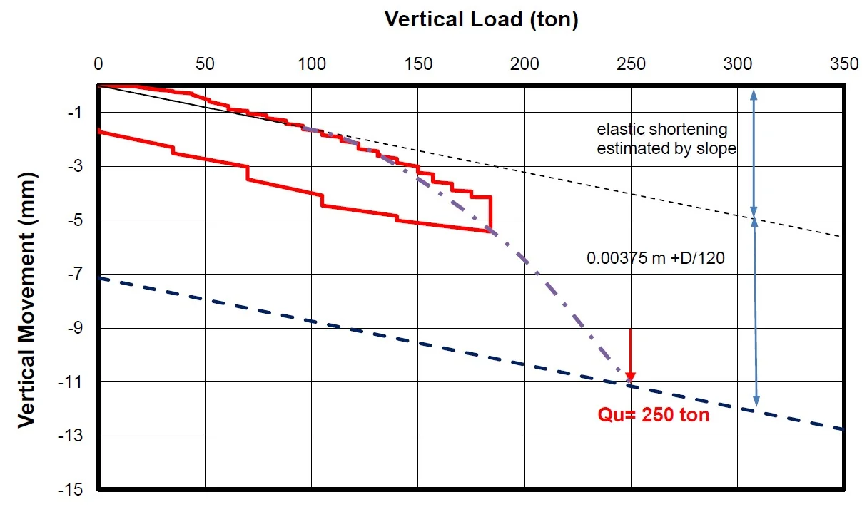
- Static — a load–settlement table for each load step and the load-settlement curve
- Seismic — the reflected-wave graph (reflectogram) of each pile used to assess integrity
Raw data matters because it allows another engineer to review the results. If a report gives only summary figures without graphs, you simply have to take the author's word for it.
5. Analysis and load capacity
A summary of the analysis results and the method used, e.g. CAPWAP for PDA or reading the curve by the Davisson criterion for a Static Load Test, together with the assessed load capacity and associated settlement.
This part gives the report its design value, because the design engineer uses the analyzed load capacity in the foundation calculations, within the ceiling set by the Ministerial Regulation (see The 40/50/40 criteria under the Foundation Ministerial Regulation B.E. 2566 (2023))
6. Conclusion against the project criteria
The report concludes whether the results meet the criteria set by the design engineer. The point to be clear on is that the acceptance criteria are values specified in each project's specifications, not values the testing provider sets on its own in place of the responsible engineer. The tester's job is to report what was measured and analyzed; deciding pass or fail is the authority of the design engineer.
7. Signature and registration number of the certifying engineer
The most important part that gives the report professional weight is the signature of a civil engineer licensed by the Council of Engineers Thailand (COE), with registration number, because it shows that a person takes professional responsibility for the results. A report without an engineer's signature is hard to use as a supporting document for a submission. Check that the engineer's name and registration number match (read more about engineer license grades and scope of work in Engineering licenses and building law)
8. Appendices and supporting documents
Site photos taken during testing, a location plan of the tested piles, equipment calibration certificates and other reference documents that make the report traceable. A good appendix means the reviewer does not need to call with follow-up questions.
How do PDA, Static and Seismic reports differ?
All three report types use the same 8-part structure but differ in the type of raw data, the analysis method and the reference standards. A PDA report focuses on signals from the hammer blow and CAPWAP analysis results; a Static Load Test report focuses on the load-settlement curve from actual loading; and a Seismic report focuses on reflectograms for assessing defects in the pile shaft (for a full PDA vs. static comparison see Dynamic vs Static Load Test)
- PDA report — Force & Velocity graphs, CAPWAP analysis results, assessed load capacity, reference to DPT 1252-51. For how to read the results see How to read PDA Test results
- Static report — load-settlement table and curve, interpretation by the Davisson criterion, reference to DPT 1251 and ASTM D1143. Details on reading the results are in Reading Static Load Test results
- Seismic report — reflectograms for assessing defects, reference to DPT 1551-51. See examples of signal interpretation in Reading Seismic Integrity Test results
Before submitting a report, try tracing it back as in the figure. Each part of the report must link to something real, e.g. row P-04 in the results table must match the pile tagged P-04 and its location on the foundation plan. The box on the right lists 6 points you can check yourself from the document.
How can a pile test report be used in a building permit application?
A report certified by a civil engineer licensed by the Council of Engineers Thailand (COE), with signature and registration number, can be used to support a building permit application to the relevant authority, because it shows that the load capacity or integrity of the piles has been confirmed by a person qualified under professional law. In practice, the design engineer cites values from the report in the signed foundation calculations (for an overview see Does the law require pile testing?)
Points to note before use:
- Trace the report back before submitting, as in the figure above: pile numbers match the foundation plan, equipment serial numbers match the calibration certificates, raw-data graphs exist for every pile, and there is a signature with the COE license registration number.
- SPN certifies its reports through its own engineers; it is not affiliated with or specifically accredited by any particular agency.
- Approval depends on the documents and the overall conditions of the project, so no service provider can guarantee that a submission will definitely pass or be approved.
- Check with the responsible engineer early on for any additional documents the local authority requires (see the overall process in Building permit steps)
To compare with the documentation checklist for soil investigation, read What a soil investigation report needs for a permit submission, which follows the same principle: complete raw data, complete analysis, and certification by a licensed engineer.
Summary
A pile test report that is genuinely usable must have all 8 elements: project and pile information, test method and reference standards, equipment and calibration information, raw data and graphs, analysis and load capacity, a conclusion against the project criteria, the COE-licensed engineer's signature, and appendices. Every part should be traceable back to the actual pile and the equipment used. The essential point is certification by a licensed civil engineer (COE), which allows the report to support a building permit application. See the full scope of services at Pile Testing Services
This article is a guide to checking document completeness for general understanding only. It is not legal or engineering advice for any particular project. Requirements of each project and of the permitting authority in each area may differ; follow the project specifications and the advice of the project's licensed engineer.