The question “how much load can the soil carry?” lies behind every type of foundation design, from houses to factories. This article explains the key concepts without equations, with 2D diagrams and a 3D model, so that project owners and engineers can speak the same language.
How does soil "fail"? Two conditions every foundation must satisfy
When a foundation presses its load onto the soil, there are 2 risks that engineers must always check:
1. Shear failure
If the load exceeds the soil's strength, the soil beneath the foundation shears and squeezes out sideways, and the foundation sinks suddenly. This limit is called the Ultimate Bearing Capacity — the ultimate load capacity of the soil.
2. Excessive settlement
The soil may not fail outright, but it can gradually compress until the building settles, cracks or tilts — especially differential settlement, where different parts of the building settle by different amounts, which is more dangerous than the whole building settling uniformly. Soft clays such as the Bangkok subsoil are usually governed by this condition rather than by shear failure (see the warning signs of a building in trouble in Signs of foundation problems)
Foundation design must satisfy both conditions at the same time — the soil does not fail and settlement stays within acceptable limits. Passing only one is not enough.
The figure below summarizes these two conditions as a 2D diagram: on the left, the shear failure mechanism beneath a footing; on the right, differential settlement that cracks a building; and a pressure–settlement graph showing that the design value comes from whichever condition gives the lower value.
What is the difference between ultimate and allowable bearing capacity?
← Scroll to see the full table →
| Term | Meaning |
|---|---|
| Ultimate Bearing Capacity (qu) | The maximum load the soil can carry before shear failure |
| Allowable / Safe Bearing Capacity (qa) | The value actually used in design, obtained by dividing the ultimate value by the factor of safety and then checking the settlement condition |
| Factor of Safety (FS) | A divisor that allows for uncertainty in the soil and loads: typically about 2.5–3 for shallow foundations and about 2.0–2.5 for piles; the actual value is at the discretion of the design engineer |
The value shown in a soil investigation report, or used by engineers to design foundations, is the allowable value, which is always lower than the ultimate value to allow for uncertainty in the soil and the actual service loads.
The allowable value is the lower of two conditions: the ultimate value divided by FS, and the pressure that causes the soil to settle by the acceptable amount. In soft clay, the settlement condition usually governs, so you should not look at the bearing capacity figure alone.
What makes soil bearing capacity differ from one plot to another?
- Soil type — dense sand and stiff clay carry load well; soft clay, mud or new fill carry little
- Foundation depth — a deeper foundation benefits from more overburden soil around it, so its bearing capacity is higher
- Foundation size and shape — a wide footing distributes load differently from a narrow one and influences the soil to a greater depth
- Groundwater level — a high water table reduces the effective unit weight of the soil, and the bearing capacity falls accordingly (read more in How the groundwater level affects foundations)
- Loading conditions — long-term sustained loads and short-term temporary loads produce different soil behavior, especially in clay
Half of the variables are "about the soil" and the other half are "about the foundation being designed" — which is why soil bearing capacity must be analyzed project by project and cannot simply be copied from the neighboring plot. It is also why using presumed values without soil boring is risky (read more in Can you use presumptive bearing values without a soil test?)
Which tests determine soil bearing capacity?
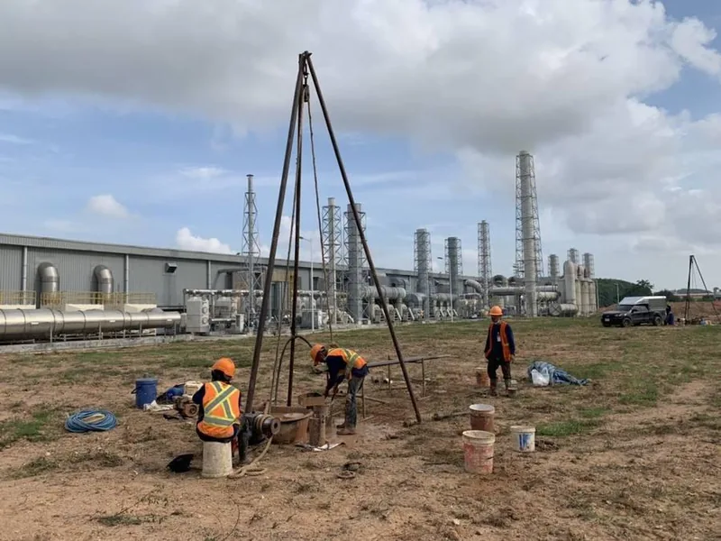
From soil investigation (soil boring)
- SPT N-value (ASTM D1586) — the standard penetration resistance recorded at every depth interval, used to assess the density of sand and the consistency of clay and then correlated to soil strength parameters — for how to interpret it, see How to interpret the SPT N-value
- Unconfined Compression Test (ASTM D2166) — determines the undrained shear strength (Su) of clay, used directly to calculate the bearing capacity of footings and piles in clay layers
- Consolidation Test (ASTM D2435) — used to check the second condition by predicting the magnitude and time of settlement (see the full list of laboratory tests in Guide to laboratory soil testing)
From direct field testing
- Plate Bearing Test (ASTM D1195/D1196 · DPT 1253-62) — a steel plate is loaded on the actual soil or fill layer to measure the load–settlement relationship directly; commonly used for factory floors, storage yards and roadwork
- Pile testing such as the Static Load Test and Dynamic Load Test (PDA) — proves the load capacity of piles as actually constructed (static per ASTM D1143 · DPT 1251; dynamic per DPT 1252-51 · ASTM D4945)

The 3D model below shows where each type of data comes from on site, and which condition each value answers, before the engineer concludes the allowable bearing capacity in the report.
How does soil bearing capacity relate to choosing spread footings or piles?
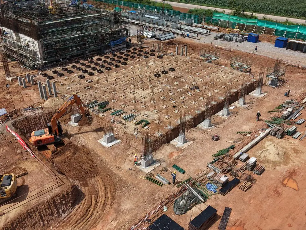
The basic principle: if the shallow soil has a high enough allowable bearing capacity and settlement stays within limits, a shallow foundation (spread footing) may be used. But if the shallow soil is too weak — such as Bangkok soft clay — piles are needed to transfer the load to a stiff soil or dense sand layer below (compare pile types in Driven, bored or spun piles: which to choose)
How deep the firm layer is and how thick it is can only be answered by soil investigation (see guidance on the number and depth of boreholes in How many boreholes, and how deep?). The final decision rests with the design engineer, based on the actual soil data for the construction plot.
Summary: how much the soil can carry can only be answered with real soil data
Bearing capacity answers the question "how much load can the soil carry without failing or settling excessively?" It depends on both the soil and the foundation, so it must come from soil investigation and testing on the actual construction plot, analyzed and certified by an engineer — not a ready-made figure that can be reused from one plot to another.
This article is provided as engineering knowledge. Determining the allowable bearing capacity and selecting the foundation system are the responsibility of a licensed design engineer, based on the project's actual soil data.