What Is a Static Pile Load Test?

A Static Pile Load Test (testing pile load capacity by the static method) applies real static load to the pile head in increments and measures the resulting settlement to build a load–settlement relationship (Load-Settlement Curve) and assess the pile's load capacity per ASTM D1143 and DPT standard 1251 (for axial compression).

In the construction industry it is often simply called a Static Test or Pile Load Test, where Pile Load Test is the umbrella term for all types of pile load capacity testing. The static method is the original and most straightforward form because it directly measures the actual load-bearing behavior. The Static Load Test is therefore regarded as the most accurate and reliable method and serves as the "reference standard" for calibrating results from dynamic methods such as PDA.
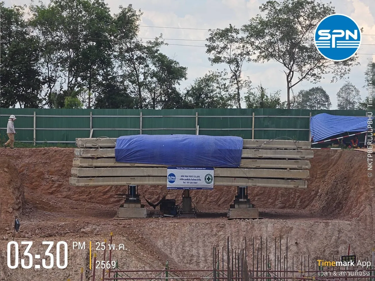
Static Pile Load Test with a kentledge system, supporting beams stacked above the test pile, with an SPN Pile Test sign
Static Pile Load Test with a kentledge system — the jack pushes on the pile head against the weight platform while settlement is measured (Photo: SPN Soil Engineering)

What Reaction Systems Are Used in a Static Load Test?

There are 2 main reaction systems: kentledge and anchor piles. Both provide the reaction against which the jack pushes down on the pile head:

  • Kentledge (dead weight) — a weight platform, such as concrete or steel blocks, is placed above the pile, and the jack pushes up against it. Suitable for moderate test loads where there is room to place the weight.
  • Reaction / Anchor Pile — anchor piles are installed around the test pile and tied to a reaction beam, and the jack pushes against the beam. Suitable for high test loads.

The choice of system depends on the test load, site space and transport of the kentledge. See a comparison and installation steps for each at Kentledge vs Reaction Piles — Which Static Load Test Setup Is Better?

A crane lifting supporting beams to set up a kentledge platform in a large foundation excavation, by the SPN team
Installing a kentledge system — a crane lifts the supporting beams into position above the test pile in a foundation excavation (Photo: SPN Soil Engineering)

Kentledge System on Real Sites

3D diagram of a kentledge system for a Static Pile Load Test, showing a concrete weight platform on steel beams and a hydraulic jack at the center
Kentledge system diagram — a concrete weight platform sits on steel beams, with a hydraulic jack at the center pushing up off the pile head (Image: SPN Soil Engineering)
Concrete-block kentledge platform installed above a test pile on an SPN Soil Engineering site, with the engineering team
Concrete kentledge platform installed above the test pile with reaction beams
Tarpaulin-covered kentledge platform installed above a test pile in a foundation excavation
Kentledge platform installed above the test pile in a foundation excavation
Front view of a kentledge platform, concrete blocks stacked on steel beams above the test pile head
Front view of the kentledge platform — concrete blocks stacked on steel beams
A crane stacking concrete blocks into a kentledge platform for a Static Pile Load Test on a site in Ayutthaya province
A crane stacking concrete blocks to form a kentledge platform (Ayutthaya)
Concrete-block kentledge platform covered with a rain tarpaulin, with an SPN project sign, above the test pile
Kentledge platform covered with a rain tarpaulin, with the full instrumentation set installed
Kentledge platform on supporting beams with a pile-driving rig at a Static Load Test site
Kentledge platform on supporting beams in the middle of a pile-driving site

Reaction / Anchor Pile System on Real Sites

Diagram of a reaction/anchor pile system for a Static Pile Load Test, showing the test pile in the center, hydraulic jack, reaction beam, anchor piles on both sides and reference beam with settlement gauges
Reaction/anchor pile system diagram — the jack pushes on the test pile head against a reaction beam tied to anchor piles on both sides, with settlement measured from the reference beam (Ref. Beam)
Anchor pile system and steel reaction beam on a real site, SPN engineers installing measuring instruments for a Static Pile Load Test
Steel reaction beam tied to anchor piles on site during installation of measuring instruments
An SPN engineer reading instruments at the anchor pile system and steel reaction beam during a Static Pile Load Test on site
An engineer reading the instruments during a test using the anchor pile system

How Is Load Applied in a Static Load Test?

The most common method is Maintained Load: load is added in increments, e.g. 25% of the design load per increment, with each increment held until settlement stabilizes before the next is added. There are 3 main loading procedures:

  • Maintained Load (ML / Slow ML) — load is added in increments, each held until settlement stabilizes. This is the standard and most widely used method.
  • Quick Maintained Load (QML) — each increment is held for a short, fixed time, so testing is faster.
  • Constant Rate of Penetration (CRP) — the settlement rate is controlled to remain constant; suitable for determining ultimate capacity.

A proof test usually loads to 2–3 times the design load (depending on each project's specification), while a test to determine ultimate capacity loads the pile until it fails or settles to the criterion. The load is then released in increments to measure rebound and residual settlement.

Which Formulas Are Used to Interpret a Static Load Test?

There are 3 key formulas: elastic shortening of the pile, the Davisson criterion and the allowable working load. All are used to separate the elastic shortening of the pile itself from settlement caused by the soil:

Elastic shortening of the pile:   δ = P · L / ( A · E ) P = load, L = pile length, A = cross-sectional area, E = modulus of elasticity
Davisson criterion (Offset Limit):   Sf = P·L/(A·E) + ( 3.8 + D/120 ) Units in millimeters, D = pile diameter (mm) — the ultimate capacity is where the curve intersects this offset line
Allowable working load:   Qallow = Qult / FS FS = factor of safety, typically about 2.0–2.5

How Do You Read the Load-Settlement Curve?

The load–settlement curve is the main result of the test. It shows the ultimate capacity, the settlement at the test load and the residual settlement after unloading. Common methods to determine ultimate capacity include:

  • Davisson Offset Limit — the most widely used criterion: a line is drawn parallel to the elastic shortening line and shifted by an offset.
  • Settlement Criteria — e.g. limiting total settlement or residual settlement to a specified value.
  • Other methods — e.g. Chin-Kondner and Brinch Hansen 80% for mathematical estimation.

For an in-depth look at reading the curve and step-by-step interpretation examples, continue to How to Read Static Load Test Results — Load-Settlement Curves and Davisson. If the results fail the criteria, see the check sequence and remedial options at Failed Static Load Test? What to Do

The diagram below links the loading method to reading the results. The left side shows load added in increments and settlement over time, which must stabilize at every increment. The right side plots the end value of each increment as a Load-Settlement curve and finds its intersection with the Davisson line, offset from the PL/AE line by (4 + D/120) mm. (The 4 mm is rounded from 0.15 in ≈ 3.8 mm in Davisson's original.)

Maintained Load loading principle in a Static Pile Load Test and reading the Load–Settlement curve with the Davisson criterion (illustrative example) A two-panel diagram arranged left and right; an illustrative example with assumed values, not actual test results. The left panel is a two-tier chart sharing a time axis. The upper tier is a stepped load–time chart, with load added one increment at a time, 25 percent of the design load per increment, up to a maximum test load of 200 percent, then released in increments to zero. The hold periods of later increments are longer because settlement must stabilize. The lower tier is a settlement–time chart: each time load is added, the pile settles immediately and then gradually slows until it stabilizes before the next increment. On unloading, the pile partly rebounds and residual settlement remains. The right panel is a load–settlement chart plotting the end value of each increment, with the elastic shortening line PL/AE and the parallel Davisson line offset by 4 plus D divided by 120 millimeters. The point where the curve intersects the Davisson line is the ultimate capacity Qult, and the unloading line returns to the residual settlement. The bottom strip summarizes three items: a proof test loads to 2 to 3 times the design load per the project specification; the Davisson criterion formula; and the working load equals the ultimate capacity divided by a factor of safety of about 2.0 to 2.5. Principle: load in increments → read with Davisson criterion Not to scale 1 Loading steps (Maintained Load) Conceptual example · Assumed values Load → 100% 200% ← Settles Time → +25% per step of design load Max. test load Unload in steps Hold until stable then next step Residual Orange band = 1 step hold End of each step → plotted in chart 2 2 Results: Load–Settlement curve Find ultimate (Qult) by Davisson Load P → ← Settles offset 4 + D/120 mm Qult Loading (step end values) Unload → residual Elastic PL/AE Davisson line Qult = curve meets Davisson line 1 Proof Test 2–3× design load (per spec) 2 Davisson criterion S = PL/AE + (4 + D/120) mm 3 Working load Qallow = Qult / FS (≈ 2.0–2.5)
Maintained Load loading principle (25% of the design load per increment up to 200%, then unloading in increments) and reading the Load-Settlement curve: the point where the curve intersects the Davisson line is the ultimate capacity (Qult) — illustrative example with assumed values, not actual test results; the test load and criteria actually used follow the project specification

What Are the Steps of a Static Load Test?

Testing one pile involves 6 main steps, from installing the reaction system to preparing the report:

  1. Install the reaction system (kentledge or reaction piles + reaction beam)
  2. Place the hydraulic jack with a load cell on the test pile head
  3. Install settlement gauges (dial gauges/LVDTs) at 2–4 points on independent reference beams
  4. Apply load in increments, hold each until settlement stabilizes, and record readings
  5. Increase to the test load (2–3 times per the project specification, or to failure), then unload in increments
  6. Plot the Load-Settlement curve, analyze with Davisson and prepare the report
Static Pile Load Test in progress — hydraulic jack on the pile head beneath the kentledge platform, with settlement gauges on blue independent reference beams, by the SPN engineering team
Actual field test — hydraulic jack with load cell on the pile head beneath the kentledge platform, and settlement gauges on independent reference beams (Photo: SPN Soil Engineering)

The 3D view below shows the full equipment set on test day. The front corner of the weight blocks is cut away to reveal the jack and load cell beneath the main beams. Note that the reference beams and settlement gauges are set up independently of the weight platform and cribbing, while the hydraulic pump and datalogger are placed away from the platform.

3D model of a Static Pile Load Test kentledge setup, showing the positions of the jack, load cell, independent reference beams, settlement gauges, hydraulic pump and datalogger Conceptual 3D view of a Static Pile Load Test kentledge setup on the ground, with the front-right corner of the kentledge blocks partly cut away to show the interior. Letters A to J in the image are explained in the caption: A, concrete kentledge blocks stacked in two layers; B, secondary beams laid across the main beams; C, twin steel main beams spanning over the pile head; D, two cribbing stacks supporting the ends of the main beams; E, hydraulic jack and load cell on the steel plate at the pile head pushing up against the underside of the main beams; F, four dial gauges or LVDTs measuring settlement; G, two blue independent reference beams on supports located outside the weight platform; H, hydraulic pump with pressure gauge connected by hydraulic hose to the jack; I, datalogger receiving signal cables from the load cell and gauges; and J, the test pile head. The panel on the right lists six test steps: install the reaction system; place the jack and load cell on the pile head; install gauges on independent reference beams at two to four points; apply load in increments and hold until settlement stabilizes, then record; increase to the test load of 2 to 3 times the design load per the project specification, or to failure, then unload in increments; and plot the curve, analyze with the Davisson criterion and prepare a report certified by a licensed civil engineer. 3D model: kentledge test setup and instrument positions Not to scale A B C D E F G H I J A Kentledge (concrete blocks) B Secondary beam C Twin steel main beam D Cribbing stacks J Test pile head + steel plate E Hydraulic jack + load cell F Dial gauge / LVDT ×4 G Indep. ref. beam ×2 (supports outside) H Hydraulic pump + pressure gauge I Datalogger, auto recording Test sequence, 1 pile 1 Install reaction system Cribbing · main · secondary · blocks 2 Place jack + load cell On test pile head steel plate 3 Install settlement gauges On indep. ref. beams, 2–4 points 4 Stepwise loading Hold until stable, then record 5 To test load → unload 2–3× or to failure · unload in steps 6 Curve + Davisson → report Certified by licensed civil eng. Conceptual Front blocks cut away to show inside System size and gauge count follow the project specification Pump & datalogger set away
3D model of a Static Load Test kentledge setup showing the hydraulic jack + load cell on the pile head, 2 independent reference beams with 4 settlement gauges, the hydraulic pump and datalogger, with the 6-step test sequence — conceptual view, blocks partly cut away to show the interior, not to scale

What Are the Advantages and Limitations of a Static Load Test?

The main advantage is accuracy from measuring actual behavior; the main limitations are time and cost:

✅ Advantages

The most accurate and reliable method, because it directly measures actual load-bearing behavior. It is the reference standard used to calibrate other methods and provides a complete Load-Settlement curve.

⚠️ Limitations

Time-consuming (possibly several days per pile), costly, and requires a large reaction system, so usually only selected sample piles are tested, and sufficient site space must be prepared. See the timeline for each step at How Many Days Does a Static Load Test Take?

Static Load Test fees are generally about THB 50,000–150,000+ per pile, depending on the test load, reaction system and site conditions. This price excludes travel and equipment mobilization, which are charged extra based on the distance to the site. See prices for each pile test method at Pile Testing Prices 2026

Which Standards Apply to a Static Load Test?

Axial compression Static Load Tests in Thailand refer to 2 main standards: ASTM D1143 and DPT standard 1251:

  • ASTM D1143/D1143M-20e1 (Standard Test Methods for Deep Foundation Elements Under Static Axial Compressive Load) — specifies the loading system, incremental loading procedure, settlement measurement and reporting.
  • DPT standard 1251 (Standard for Static Load Testing of Pile Bearing Capacity) of the Department of Public Works and Town & Country Planning — widely referenced on construction projects in Thailand.

The test report must state the standard used, the test load and the Load-Settlement curve. SPN reports are certified by a civil engineer holding a professional engineering license (COE) from the Council of Engineers Thailand and can be submitted for building permits to the relevant authorities. See further legal requirements at The Foundation Ministerial Regulation B.E. 2566 (2023) and Pile Testing

How Does a Static Load Test Differ from Other Pile Test Methods?

A Static Load Test measures load capacity with real load and is the reference standard, while other methods focus on speed and the number of piles that can be tested:

← Scroll to see the full table →

Test method / standardWhat it measures and key features
Static Load Test (ASTM D1143)Load capacity with real load; most accurate and the reference standard, but slow and costly
Dynamic Load Test — PDA (ASTM D4945)Load capacity by high-strain impact; fast, economical, can test many piles
Seismic / Low Strain (DPT 1551-51 · ASTM D5882-16, withdrawn in 2025)Integrity and length only, by low-strain impact; does not assess load capacity

Typically a Static Load Test is used on sample piles to confirm capacity, and then a Dynamic Load Test (PDA) is used to check a large number of piles. Read an in-depth comparison at Dynamic vs Static Load Test: Which Should You Choose?, see "integrity" testing at Seismic Test (Low Strain), or see SPN's full range of pile testing services

📌 Note

This article is provided as engineering knowledge. The choice of reaction system, loading method, test load and interpretation criteria should follow the project specification and the judgment of a licensed engineer.