What Is a Seismic Test (Low Strain Pile Integrity Test)?
A seismic test, or low strain pile integrity test (also called a Pile Integrity Test — PIT, or Sonic Echo), is a non-destructive test of pile integrity. The pile head is tapped with a hand-held hammer and the reflected wave is measured. A low-strain stress wave travels down the pile and is reflected back when it meets a change in cross-section or impedance, such as a defect or the pile toe. An accelerometer mounted on the pile head records this signal for analysis.
In Thailand, the Department of Public Works and Town & Country Planning standard DPT 1551-51 (standard for pile integrity testing) is the main criterion. The international test method most often cited is ASTM D5882-16, which ASTM withdrew in 2025. If ASTM is cited in documents, the edition year and status should therefore be stated clearly.
The seismic test is a very popular quality control (QC) method for bored piles and cast-in-place piles, and can also be used on precast piles, because it is fast, economical and can test large numbers of piles without pre-installed tubes as required by cross-hole sonic logging.
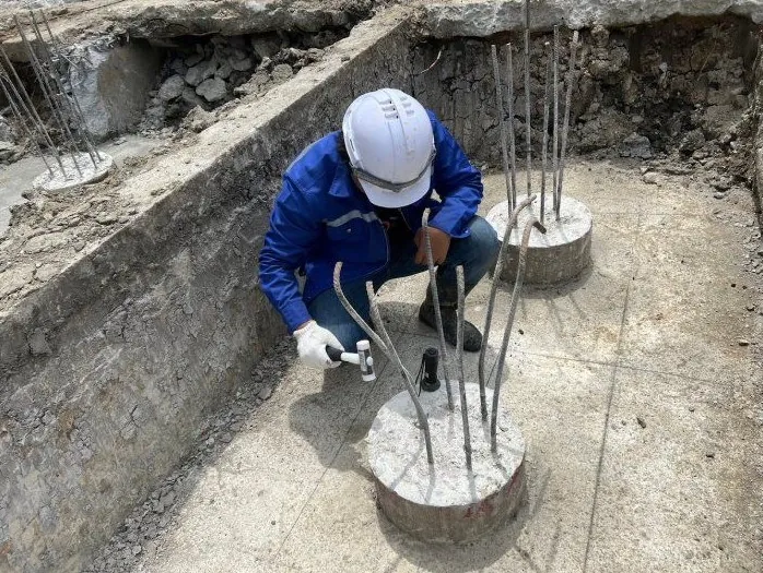
Why Check Pile Integrity?
Because pile defects occur underground and cannot be seen from outside. Cast-in-place bored piles can be unintentionally defective during construction—for example, borehole wall collapse causing necking, concrete segregation forming voids, or soil mixed into the concrete. Precast piles may crack during handling or driving.
If left undetected, a pile may not carry its full load and may settle later. Integrity testing is therefore an important screening step before the superstructure is built.
How Does a Seismic Test Work?
The seismic test is based on wave reflection. When the pile head is tapped, a stress wave travels down through the concrete at wave speed (c) and is reflected back up whenever it encounters a change in impedance.
There are 2 ways to analyze the signal: the time domain (Sonic Echo / Pulse Echo Method), which looks at the position and direction of reflection peaks, and the frequency domain (Transient Response Method). The direction of a reflection also indicates the type of change: necking (impedance decrease) gives a reflection in the same direction as the impact wave, while bulging (impedance increase) gives a reflection in the opposite direction.

How Is Pile Length Calculated from the Reflected Wave?
Pile length, or depth to a reflector, is calculated from L = c·Δt/2, where Δt is the time for the wave to travel down and be reflected back to the pile head. Three formulas are used for interpretation:
Hypothetical example: with c = 4,000 m/s and a toe reflection peak returning at Δt = 0.010 s (10 ms), the estimated length is 4,000 × 0.010 ÷ 2 = 20 m. With c = 3,500 m/s, it would be 17.5 m. The assumed c therefore directly affects the length.
Panel A of the figure below shows what happens in the pile when it is tapped, and panel B shows the signal recorded by the sensor. Note that the peak from the necking returns before the peak from the pile toe (2L/c).
What Can a Seismic Test Detect?
The seismic test detects significant changes in cross-section or concrete quality and can be used for a preliminary estimate of pile length, as follows:
- Necking — reduced cross-section, reduced impedance
- Bulging — increased cross-section, increased impedance
- Crack / break (Discontinuity) — causes the wave to reflect back before reaching the toe
- Void / honeycomb — concrete that is not dense and homogeneous
- Soil inclusion in concrete — from borehole wall collapse during casting
- Preliminary pile length estimate — comparing the estimated length with the design (an approximation that depends on the assumed wave speed and requires a visible toe reflection)
To see what each type of signal looks like on a plot, read How to Read Seismic Integrity Test Results and Reflectograms. And if a test shows an abnormal signal, it does not always mean the pile is unusable—see the checks and remedies engineers actually use in What to Do When a Pile Fails the Seismic Test
• The pile length shown in the report is only the length derived from the reflected wave speed, or as advised from the field. The actual length should be judged from field information.
• For tested piles, driving or boring records should be reviewed before the piles are put into service—for example, pile casting and temporary steel casing extraction records, together with soil conditions, site exposure and pile eccentricity—with the field engineer or designer making the assessment before use.
• If the pile length needs to be known, a Parallel Seismic Test is recommended
What Are the Steps of a Seismic Test?
The test has 6 main steps and takes only a few minutes per pile once the pile head has been prepared.
- Prepare the pile head — cut/grind to a sound, smooth and clean concrete surface
- Mount the accelerometer on the pile head with a coupling material
- Tap the pile head with a hand-held hammer to generate a low-strain stress wave
- Record the reflected wave signal several times and average to reduce noise
- Analyze the signal to determine length and defect locations
- Classify the integrity level and prepare a report certified by a licensed civil engineer (COE)
A pile head ready for testing must be cut or chipped down to sound concrete with a smooth, clean surface, and the concrete must be old enough per the project specifications. See details in Pile Head Preparation Before Testing and Concrete Age Required for Pile Testing
The 3D view below simulates an actual site: green pile heads have been tested, gray ones are awaiting testing, and a pile with a rough head must be chipped first. The right-hand panel summarizes what must be prepared and the sequence of work on test day.
How Much Does a Seismic Test Cost, and What Are Its Pros and Limitations?
Seismic testing starts at about THB 100–150 per pile, depending on the number of piles and site conditions. This price excludes travel and equipment mobilization, which are charged according to the site distance. Compare prices of each pile testing method in Pile Testing Prices 2026, or contact us for a free quotation within 24 hours.
Fast (a few minutes per pile), low cost, non-destructive, no pre-installed tubes and lightweight equipment, so large numbers of piles can be tested in a short time.
Suitable for piles whose length-to-diameter ratio (L/D) is not too large (about 20–30). Very long piles or piles with high skin friction damp the wave so that no toe signal is visible. This method only detects significant defects and is not a load capacity test. Results must be interpreted by an experienced engineer.
Which Standards Apply to the Seismic Test, and How Does It Differ from Other Methods?
In Thailand, the seismic test mainly references DPT 1551-51, and it is only one in a set of pile tests, each answering a different question:
← Scroll to see the full table →
| Test method / standard | What it measures and key features |
|---|---|
| Seismic / Low Strain (DPT 1551-51; ASTM D5882-16 withdrawn in 2025) | Integrity and preliminary pile length — fast, low cost, non-destructive, no tubes required, many piles can be tested, but limited by L/D |
| Cross-hole Sonic Logging (ACI PRC-228.2; ASTM D6760-16 withdrawn in 2025) | Detailed internal integrity of large piles; test tubes must be installed in advance during casting |
| Dynamic Load Test — PDA (DPT 1252-51 + ASTM D4945) | Pile load capacity using a high-strain impact; faster than static |
| Static Load Test (DPT 1251 + ASTM D1143) | Load capacity measured directly with real load; the main reference method for determining load capacity |
Typically, the seismic test is used to check the integrity of large numbers of piles, and selected piles are then tested for load capacity by dynamic (PDA) or static load test. For more on reading PDA results, see PDA Test Result Interpretation, or see the scope of all SPN pile testing methods on our pile testing services page.
Seismic Test Photos from Actual Sites
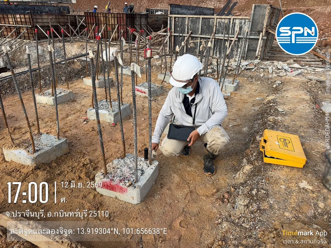
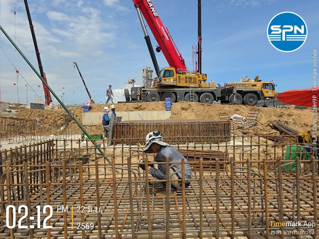
Examples of pile integrity testing by the seismic (low strain) method by the SPN Soil Engineering engineering team, on both cast-in-place bored piles and precast piles, in many types of real projects across Thailand.


This article is provided as engineering knowledge. The choice of test method, number of piles to be tested and interpretation of results should follow the project specifications and the judgment of a licensed engineer.