What Is a Dynamic Load Test (PDA Test)?
Dynamic Load Test, or PDA Test (named after the Pile Driving Analyzer instrument), is a test of pile load capacity by high-strain dynamic testing in accordance with ASTM D4945 and the Department of Public Works and Town & Country Planning standard DPT 1252-51 (Standard for Dynamic Load Testing of Piles). A drop hammer strikes the pile head to generate a stress wave, and gauges measure force and velocity at the pile head for analysis based on stress wave theory.
Besides load capacity, a single test also provides pile integrity, driving stress and transferred energy, which is why it is widely used for acceptance testing of large numbers of piles, both driven and bored.
How Does a PDA Test Work? The High-Strain Principle
PDA uses a high-energy impact to send a stress wave down the pile, then reads how much resistance the soil provides from the difference between the force and velocity signals at the pile head.
When the hammer strikes the pile head, a stress wave travels down the pile. Strain transducers and accelerometers mounted near the pile head convert the signals into “force” and “velocity” over time. In the early part of the record, before reflections arrive, force and velocity are proportional. As the soil along the shaft and at the toe resists the wave, the two signals separate, and the engineer uses this difference to evaluate load capacity. For a step-by-step guide to reading force versus Z·v plots, see PDA Test Result Interpretation

Test Setup (Side Elevation and 3D Model)
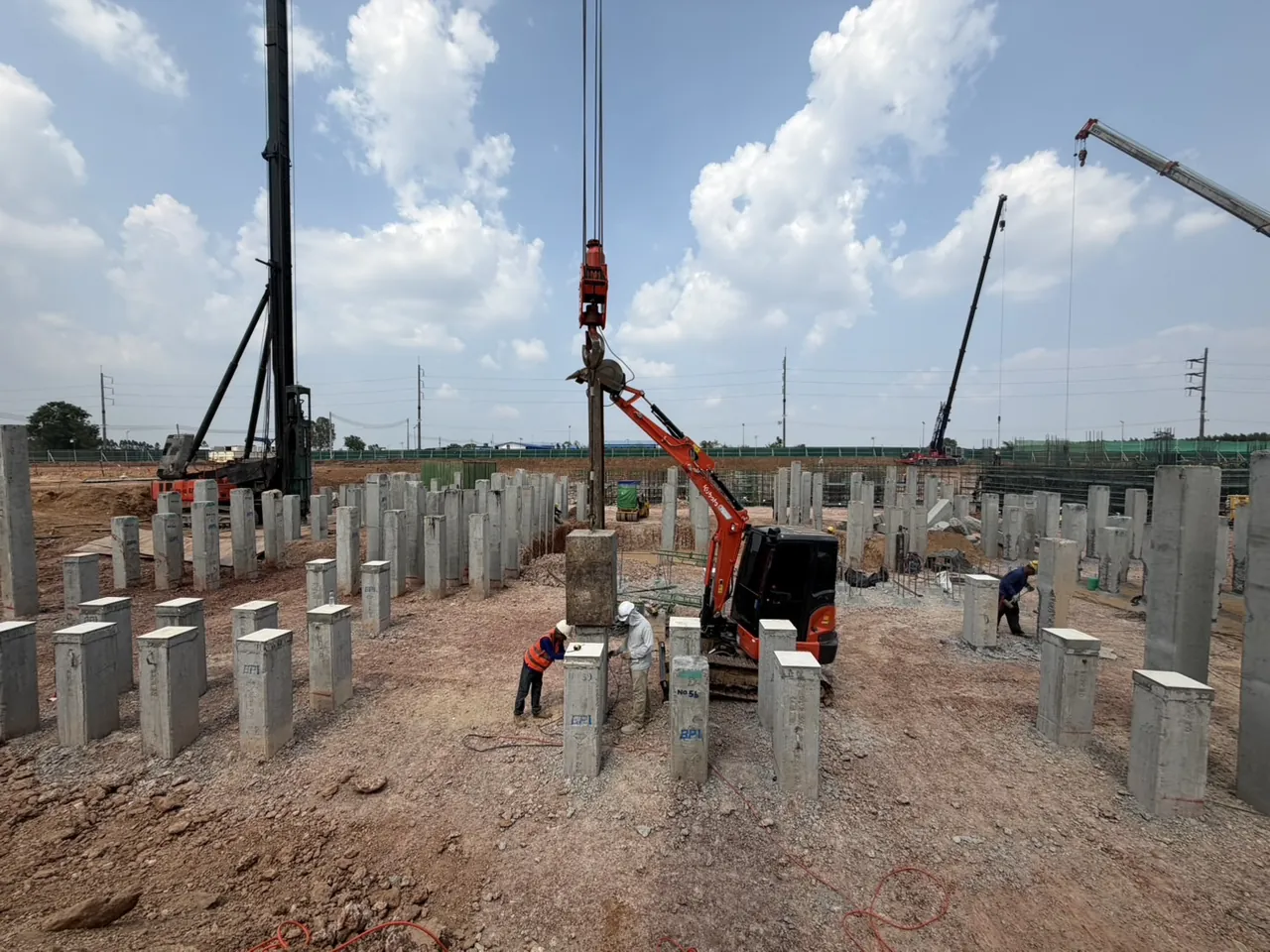
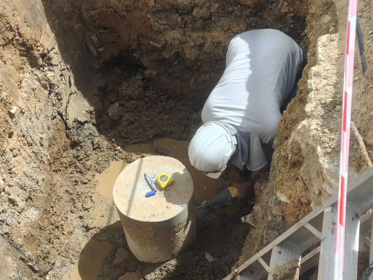
The setup consists of a crane lifting a steel hammer that drops along a hammer guide onto the pile head through a pile cushion. Before testing, a pit is excavated around the pile head with a clearance of about 0.8 m from the pile surface and a depth of about 1.5B–2.0B (B = pile cross-section size), subject to each project's specifications, so that the gauges can be mounted at least 1.5B below the pile head as required by ASTM D4945. Strain transducers and accelerometers are mounted in pairs on opposite sides of the pile, and the cables are connected to the PDA unit.


What Formulas Does PDA Use to Calculate Capacity?
PDA relies on three main formulas from stress wave theory: force from measured strain, pile impedance, and the CASE Method formula, which uses signals at two instants 2L/c apart to estimate total resistance:
What Is the Difference Between the CASE Method and CAPWAP?
The CASE Method gives an immediate estimate on site, while CAPWAP is a detailed office analysis that confirms the static capacity. PDA results are therefore analyzed at two levels:
- CASE Method — a quick closed-form calculation in the field using a soil damping factor (Jc), giving an approximate load capacity immediately on site
- CAPWAP (Signal Matching) — an in-depth office analysis that matches the measured signals to a model to obtain a reliable static capacity, together with the distribution of shaft friction, end bearing and a simulated load–settlement curve (read more in What Is CAPWAP Analysis)

What Does a PDA Test Measure?
A single PDA test provides four types of data at once:
- Load capacity — both shaft friction and end bearing
- Pile integrity (BTA) — detects cracks or reductions in cross-section
- Driving stress — maximum compressive and tensile stresses, to prevent pile damage during driving
- Transferred energy — evaluates the efficiency of the pile driver/hammer
What Are the Steps of a Dynamic Load Test?
PDA work has four stages: site preparation, field testing, CAPWAP analysis and the certified report. The first two take place on site; the last two are done in the office.
The diagram below summarizes the whole PDA process in one view. Read the cards from left to right: cards ①–② are site work and cards ③–④ are office work. Then check the bottom panels for what PDA results can answer and which questions need other methods.
The detailed steps, in the actual order of work, are:
- Trim the pile head flat and square, drill holes for gauge anchors, excavate a pit around the pile head, and set up the crane and drop hammer
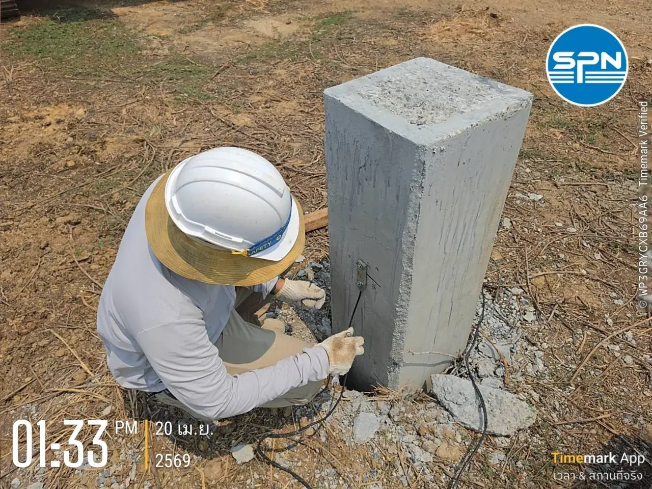
- Mount 2 strain transducers and 2 accelerometers on opposite sides of the pile, at least 1.5B below the pile head
- Drop the hammer onto the pile head (high strain) with enough energy to mobilize the soil resistance
- The PDA unit records force and velocity over time for each blow
- Make a preliminary evaluation in the field with the CASE Method
- Perform CAPWAP analysis in the office and prepare a report certified by a licensed civil engineer (COE)
Before testing, check whether the pile concrete is old enough to test, complete the pile head preparation before testing, and plan the number of piles to sample for testing to suit the size of the project
Testing during initial driving is called End of Initial Drive (EOID). However, pile capacity in clay usually increases with time (soil setup), so a repeat test after the soil has rested for 1–14 days (restrike) is commonly performed to reflect the long-term capacity.
How Long Does a PDA Test Take, and How Much Does It Cost?
Field testing takes little time per pile. A typical planning figure is about 1 day per 5–10 points when the piles are in the same area (subject to each project's specifications). CAPWAP analysis and the certified report take another few working days. For the timeline from booking to receiving the report, see How Long Does a PDA Test Take
PDA testing starts at about THB 5,500 per pile, depending on pile size, number of piles and site conditions. This price excludes travel and equipment mobilization, which are charged extra according to the distance to the site.
What Are the Advantages and Limitations of PDA Testing?
The main advantages of PDA are speed and economy; the main limitation is that it is an indirect evaluation, so the static capacity used for conclusions must come from CAPWAP analysis (the bottom panels of the diagram in the steps section summarize this).
Much faster and more economical than a Static Load Test, several piles can be tested per day, it provides capacity, integrity, driving stress and energy data together, and it can handle high-capacity piles.
A reliable static capacity must come from CAPWAP analysis because the CASE Method is an estimate. The hammer must deliver enough impact energy to fully mobilize the soil resistance. Results are an indirect dynamic evaluation, so they should be calibrated against a Static Load Test on important projects and must be interpreted by experienced engineers.
What Standards Apply to Dynamic Load Testing?
Dynamic testing in Thailand refers to two main standards: ASTM D4945 and DPT 1252-51 for PDA testing:
- ASTM D4945 (Standard Test Method for High-Strain Dynamic Testing of Deep Foundations; current edition D4945-26) — specifies gauge installation, impact energy, recording of force/velocity signals and analysis of results
- DPT 1252-51 (Standard for Dynamic Load Testing of Piles) of the Department of Public Works and Town & Country Planning — referenced in project specifications and by relevant authorities in Thailand
The test report must state the standards used and be certified by a civil engineer licensed by the Council of Engineers Thailand (COE), for use in pile acceptance with the designer and relevant authorities.
How Does PDA Differ from a Static Load Test and a Seismic Test?
PDA evaluates load capacity quickly and can test many piles. A Static Load Test measures capacity directly with real load but is slower and costlier. A Seismic Test checks only integrity and length and does not evaluate capacity:
← Scroll to see the full table →
| Test method / standard | What it measures and key features |
|---|---|
| Dynamic Load Test — PDA (ASTM D4945 + DPT 1252-51) | Load capacity + integrity + driving stress by high-strain impact; fast, economical, suits large numbers of piles |
| Static Load Test (ASTM D1143 + DPT 1251) | Direct load capacity under real load; used as the reference for calibration, but slow and costly |
| Seismic / Low Strain (DPT 1551-51) | Integrity and length only, by low-strain impact; does not evaluate load capacity |
Typically, PDA is used to test the capacity of many piles, and a few are selected for calibration by Static Load Test. For an in-depth comparison, see Dynamic vs Static Load Test: Which to Choose; for how to read the results, see PDA Test Result Interpretation; and for “integrity” checks, see Seismic Test (Low Strain)
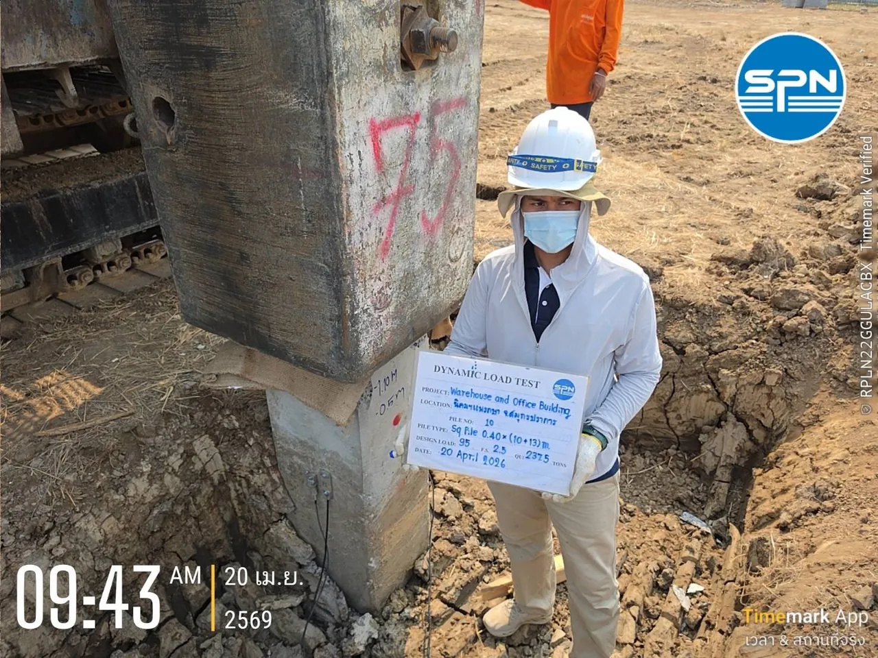
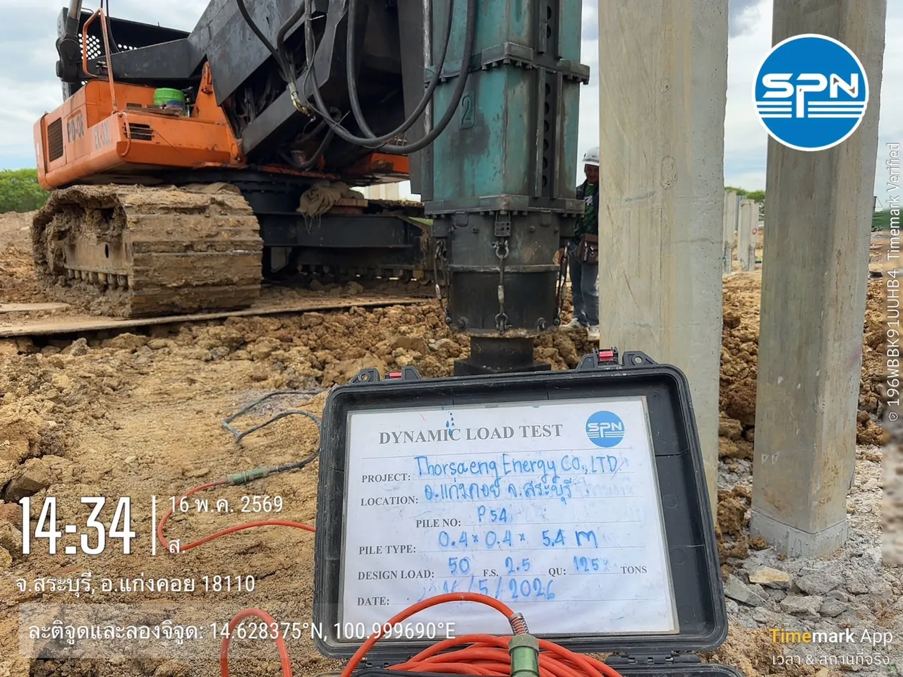
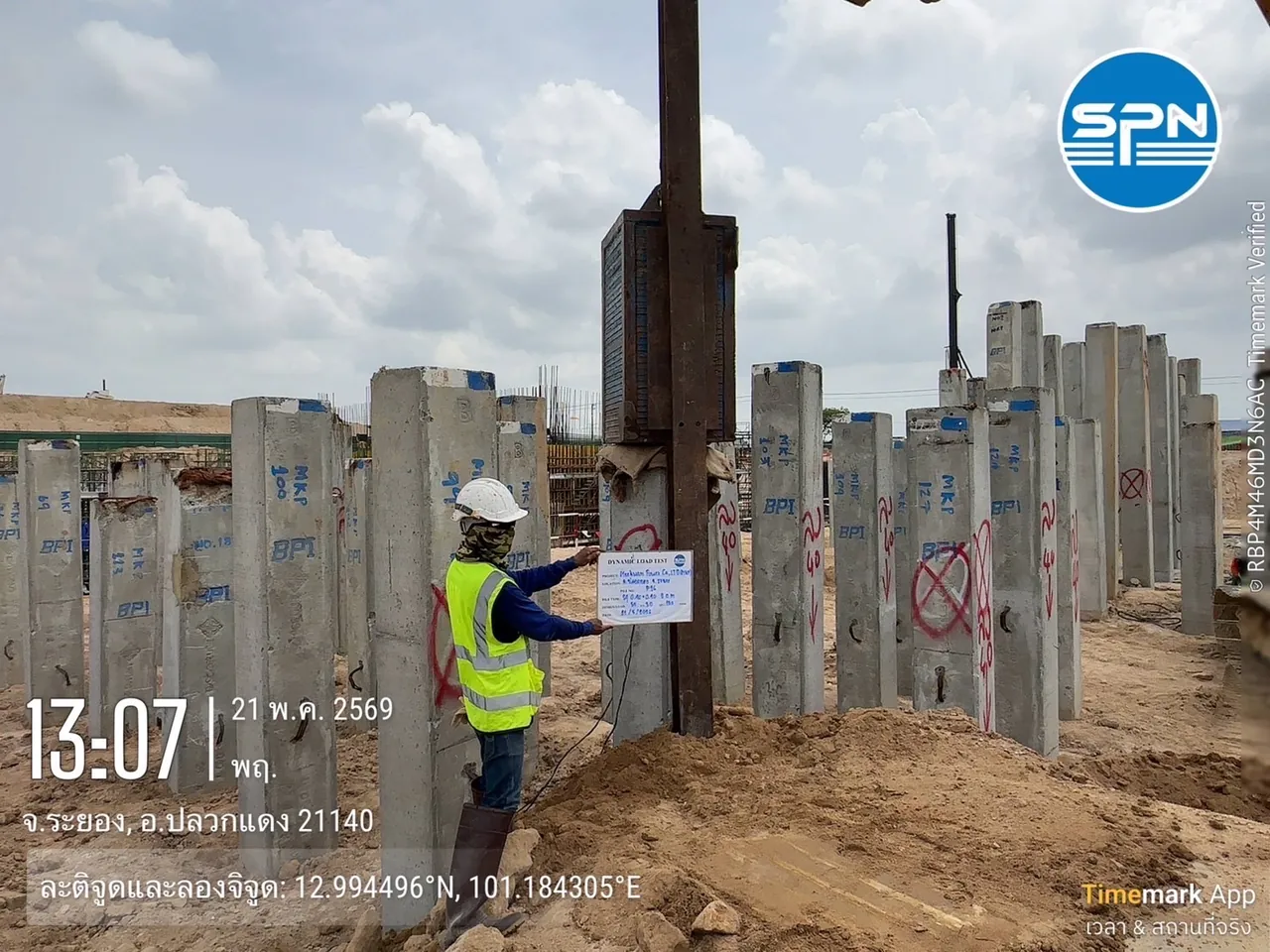
Photos from Real PDA Testing
Examples of Dynamic Load Testing (PDA) from SPN's real sites on projects across Thailand, from gauge installation and the high-energy drop hammer to the Pile Driving Analyzer in the field




This article is provided as engineering knowledge. The choice of test method, number of piles to test, damping factors and interpretation of results should follow the project specifications and the judgment of a licensed engineer.
SPN Soil Engineering provides full-service PDA testing nationwide, from field testing and CAPWAP analysis to engineer-certified reports — see the pile testing services page for details