What Is a PDA Test and What Does It Measure?
A PDA test (Pile Driving Analyzer test) determines pile load capacity by the dynamic method (dynamic load test) in accordance with ASTM D4945 and DPT 1252-51. A drop weight strikes the pile head while sensors measure force and acceleration at the pile head. The wave signals are then converted into load capacity and other check values, which the report lists as abbreviations such as RMX, EMX, FMX and CSX. For a detailed description of the field procedure, see Dynamic Load Testing of Piles (Dynamic Load Test / PDA)
What Is the Main Equipment for a PDA Test?
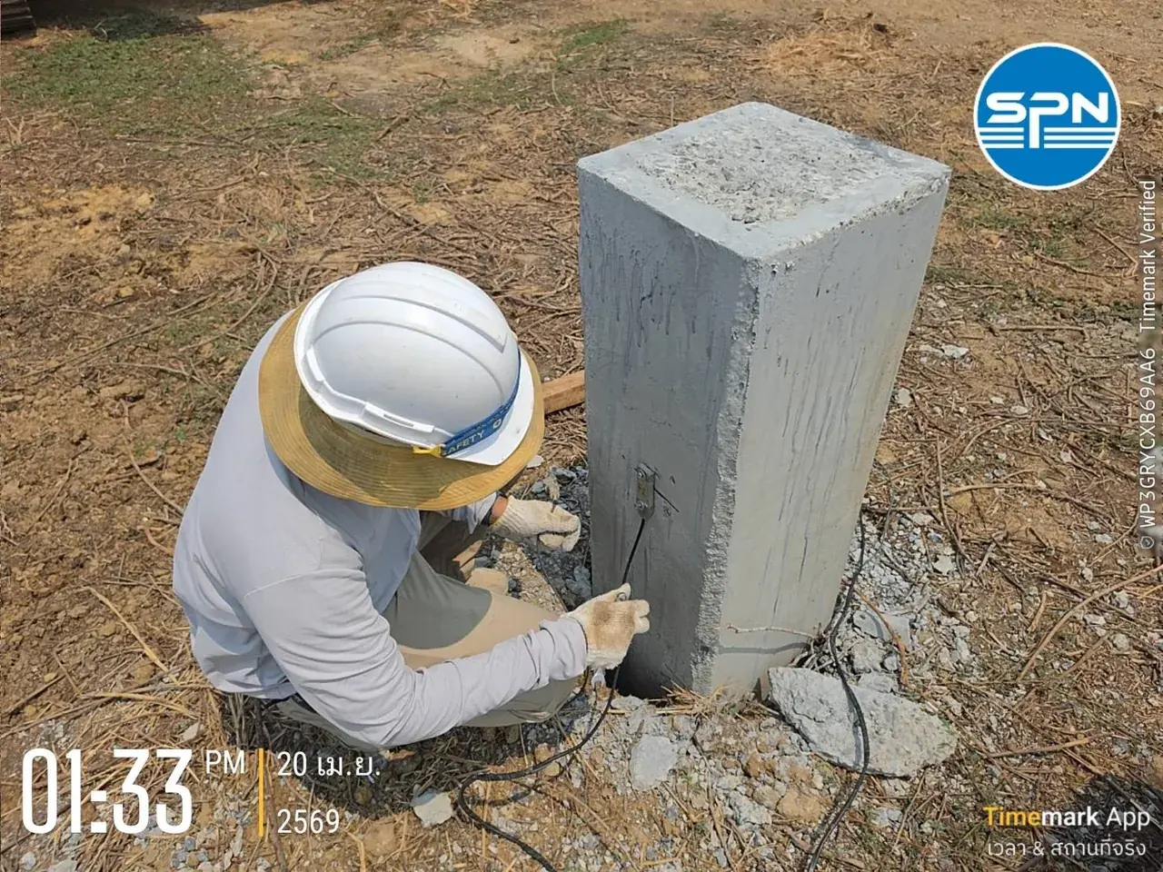
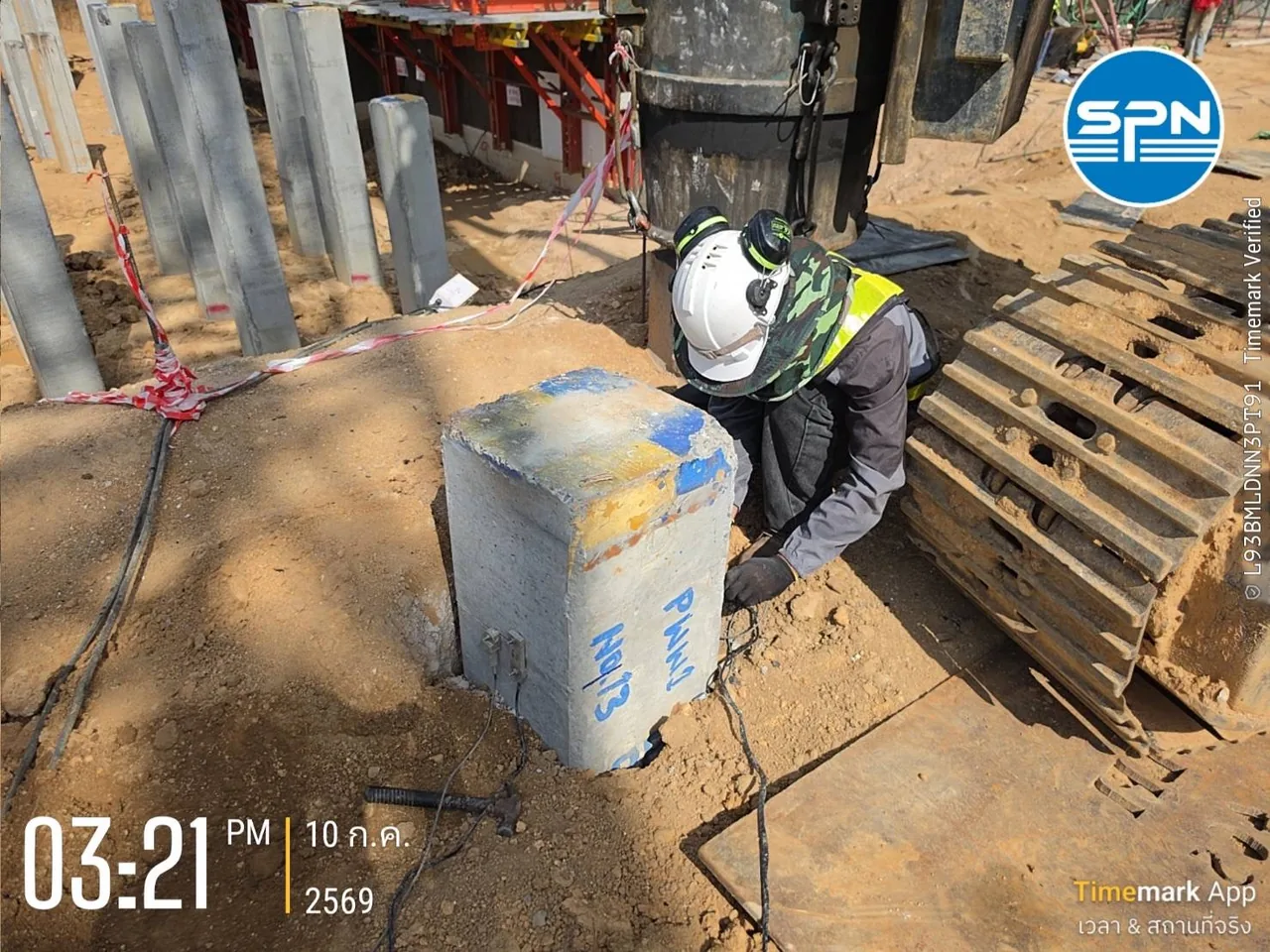
- At least 2 strain transducers mounted on opposite sides of the pile head: measure strain to compute force (large piles may use 4)
- At least 2 accelerometers mounted on opposite sides: measure acceleration, which is integrated to velocity and displacement
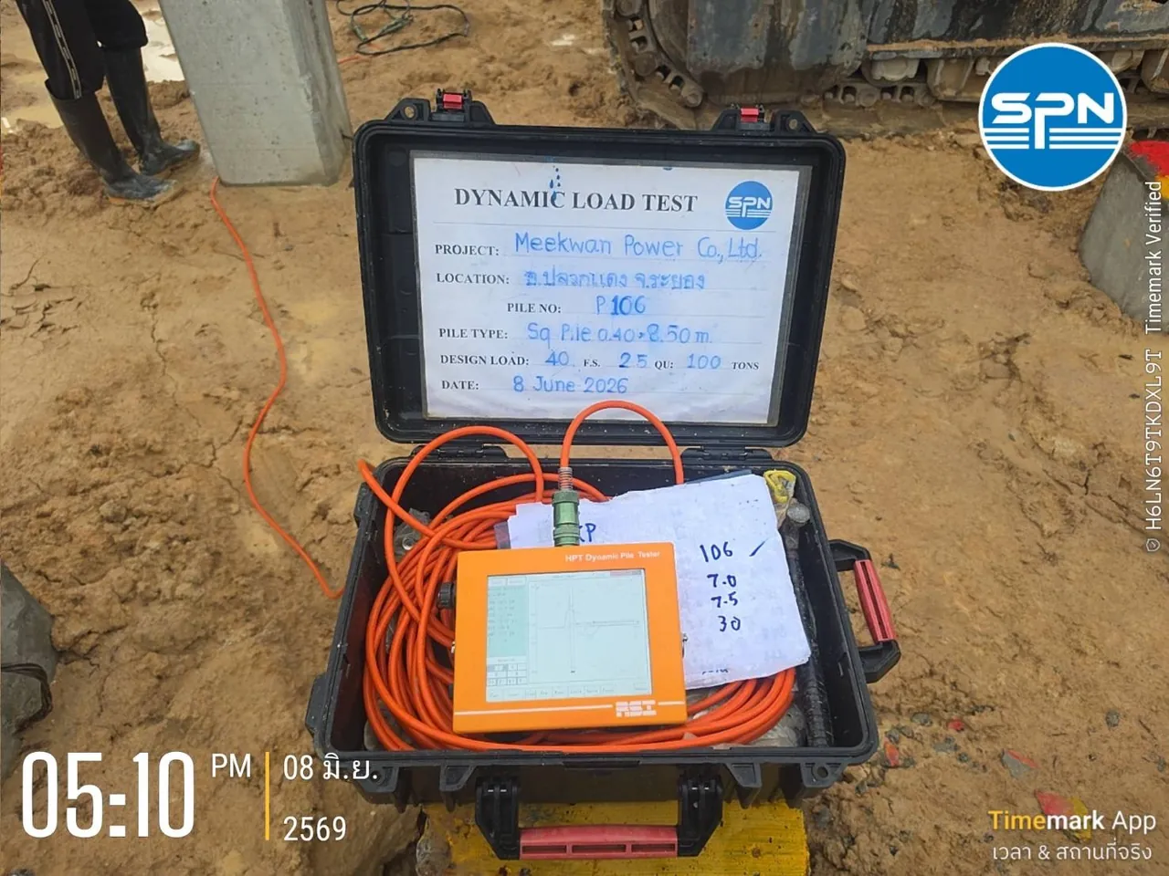
- Pile Driving Analyzer (PDA): records and processes the signals in real time
- Drop weight: approximately 1-2% of the ultimate capacity to be proven, e.g. a 2.5-5 t weight to prove 250 t
Why Check PDA Signal Quality Before Reading the Values?
Signal quality is the first gate when reading a PDA report, because every computed value, including RMX and EMX, is derived from the measured force and velocity signals. If the signals are poor, none of those values can be trusted. DPT 1252-51 (clause 4.5) clearly illustrates signals that should and should not be used:

- a) Good signal: the strain (force) and velocity curves peak together (peaks match) in the early part of the wave
- b) Good signal: signals from the same gauge pair (mounted on opposite sides of the pile) must be similar and symmetric
- c) Do not use: heavy noise — usually caused by loose sensors or faulty signal cables
- d) Do not use: peaks do not match, or the signal does not return to zero (drift) — usually caused by eccentric impact or a faulty sensor
If the report shows signals like c) or d), the field engineer must fix the sensor installation or correct the impact alignment and retest. That blow should not be used for further analysis
In the early part of the record, before the wave is reflected back from the pile toe or from soil resistance, force and velocity are proportional according to the wave equation F = Z·v, where Z is the pile impedance = EA/c (E = elastic modulus, A = cross-sectional area, c = wave speed in the pile). When velocity is multiplied by Z and the two curves overlap exactly, no resistance has been encountered yet. When the force curve and the Z·v curve separate, the wave has started to meet resistance from the soil (skin friction) or the pile toe — this is the basic principle that the Case Method and CAPWAP use to convert signals into load capacity
The diagram below combines this principle in a single chart. Point 1 is the early part where the force curve overlaps the Z·v curve, point 2 is the gap after the peak caused by shaft resistance, and point 3 is the toe response at time 2L/c. The box on the right is a quick map of the report values explained in the next section
What Do RMX, EMX and CSX Mean in a PDA Report?
RMX is the mobilized load capacity, EMX is the energy delivered to the pile, and CSX is the maximum compressive stress in the pile. They are part of a set of 8 abbreviations that summarize pile behavior for each blow, in 3 groups: capacity (RMX, RAU/RA2, Shaft/Toe), energy and force (EMX, FMX), and displacement and material stress (DMX, CSX, TSX). This table is a complete reference for all of them:
← Scroll to see the full table →
| Value | Unit | Meaning | Criterion / reference value |
|---|---|---|---|
| RMX Maximum Mobilized Capacity | kN or t | Mobilized capacity — the most important value, compared with the design working load | ≥ 2.5 × Design Working Load (FS = 2.5 under the 2023 Foundation Regulation) |
| RAU / RA2 Automatic Case Method | kN or t | Total capacity from the automatic Case Method, independent of the damping factor (J) | RAU: low shaft friction · RA2: low to moderate — used to cross-check RMX |
| Shaft / Toe Resistance (from CAPWAP) | kN or t | Separates shaft friction from end bearing by CAPWAP analysis | Ru (total capacity) = Rshaft + Rtoe |
| EMX Maximum Transferred Energy | kN·m (kJ) | Maximum energy actually transferred from the hammer into the pile in each blow | Typical energy transfer ratio ~50-70% of ram energy — below 30%, investigate the cause (a practice guideline, not a fixed criterion) |
| FMX Maximum Force | kN or t | Maximum force at the pile head | Must be large enough to mobilize soil resistance up to the level to be proven |
| DMX Maximum Displacement | mm | Maximum pile-head displacement, including elastic rebound | Read together with DFN (permanent set), which should be close to the set measured on site |
| CSX Maximum Compressive Stress | MPa or ksc | Maximum compressive stress in the pile material during impact | ≤ 0.85 × fc (concrete piles) · ≤ 0.9 × fy (steel piles), or per project specification |
| TSX Maximum Tensile Stress | MPa or ksc | Maximum tensile stress — important for long piles where a tension wave may develop during driving | Must be within the material's safe limits, per project specification |
Capacity Group — How Does RMX Differ from RAU/RA2 and Shaft/Toe?
RMX is the total load capacity computed in real time on site by the Case Method, so it is a preliminary estimate — the value used for the final conclusion must be confirmed by CAPWAP Analysis. RAU/RA2 are automatic total-capacity values that do not depend on the damping factor; engineers use them to cross-check RMX when soil conditions are uncertain. Separating shaft friction from end bearing cannot be read directly from the field values; it comes from CAPWAP analysis, which is especially important for piles that rely mainly on end bearing
← Scroll to see the full table →
| RMX vs Design Capacity | Interpretation |
|---|---|
| RMX ≥ 2.5 × Design | ✅ Passes the 2023 Foundation Regulation criterion (FS = 2.5) |
| RMX < 2.5 × Design | ❌ Fails the dynamic-method criterion — investigate the cause and consider a confirmatory static load test |
Note: The FS = 2.5 criterion follows the 2023 Foundation Regulation, which allows values from the dynamic method (dynamic load test) to be used up to no more than 40% of the ultimate resistance
Energy and Force Group — What Do EMX and FMX Tell You?
EMX indicates how efficiently the driving system delivers energy. For a free-fall drop hammer, the energy transfer ratio (EMX ÷ ram energy) is typically around 50-70%; below 30% means the system is losing a lot of energy. These figures are common practice guidelines — the criteria actually applied should follow the project specification
Common causes of low energy transfer are a worn or damaged pile cushion, a hammer out of line with the pile axis, insufficient hammer stroke, or friction in the hammer guide system; these must be corrected before retesting. FMX must be high enough to mobilize soil resistance up to the level to be proven, but whether the pile can withstand the impact without cracking is checked from the stress CSX against the material strength, not from FMX directly
Displacement and Stress Group — How to Read DMX, CSX and TSX?
DMX is the maximum displacement and includes elastic rebound, so it is not the permanent set. For the permanent set, look at DFN (final displacement), which should be close to the set measured on site. CSX and TSX are used to check the safety of the pile material: compressive stress should not exceed 0.85 × fc for concrete piles or 0.9 × fy for steel piles (or per project specification), and tensile stress needs particular attention in long piles
Many PDA reports also show BTA (β), an integrity index of the pile cross-section estimated from wave reflections arriving before the toe reflection. A value of 100% means a uniform cross-section; a lower value means there may be a change in section or damage, and an engineer should investigate further, e.g. with CAPWAP
How Do You Read a PDA Report Value by Value?
Read a PDA report one value at a time, in order: compare RMX with the design load first, then check EMX, CSX, FMX and DMX/DFN. The example below uses illustrative numbers to explain the reasoning; it is not the result of any particular project
Bored pile Ø60 cm, 24 m long, concrete fc = 30 MPa · Design load = 100 t · 5 t ram, 1 m drop height · Results: EMX = 18 kJ, FMX = 280 t, DMX = 12 mm, RMX = 260 t, CSX = 12 MPa
Value-by-value analysis
- RMX = 260 t vs design = 100 t → FS = 2.6 ✅ passes the FS = 2.5 criterion of the 2023 Foundation Regulation
- EMX = 18 kJ from a 5 t ram dropped 1 m (energy ≈ 49 kJ) → energy transfer ratio = 18/49 ≈ 37% ⚠️ above the 30% level that requires investigation but below the typical range (50-70%); check the cushion condition and the driving alignment as well
- CSX = 12 MPa vs 0.85 × 30 MPa = 25.5 MPa → ✅ compressive stress is below the material limit
- FMX = 280 t > RMX = 260 t → the impact force exceeds the level to be proven; use it together with the set (DFN/Set) to confirm that enough soil resistance was mobilized
- DMX = 12 mm → this displacement includes elastic rebound; for the permanent set, compare DFN with the set measured on site
Example summary: passes on both load capacity and stress
This pile has FS = 2.6, which is not less than 2.5, and its compressive stress is below the material limit. However, RMX is a Case Method value, so the value reported in the conclusion should be confirmed by CAPWAP, and the design engineer should review it together with the results of the other test piles in the project
What Is CAPWAP Analysis and Why Is It Needed?
CAPWAP (CAse Pile Wave Analysis Program) is a program for in-depth analysis of PDA signals using signal matching. After the field signals are obtained, engineers run CAPWAP to:
- Separate the load capacity into shaft and toe components
- Simulate a load-settlement curve for comparison with static load test results
- Assess pile integrity along the full length and detect defects
- Adjust damping and quake values to match actual soil conditions

This article gives only an overview of CAPWAP — for an in-depth look at signal matching, its outputs, and a comparison of CAPWAP vs Case Method vs static load test, see What Is CAPWAP? Why PDA Test Results Need CAPWAP Analysis
The 3D view below traces the data path from the sensors at the pile head, to the PDA unit that computes the Case Method on site, through to CAPWAP, which produces the shaft/toe resistance distribution and a simulated load–settlement curve. The box on the right is a 7-point checklist for reviewing a report before drawing conclusions
When Does a PDA Test Pass — How Many Times the Design Load?
A PDA test passes on load capacity when RMX is at least 2.5 times the design working load. In Thailand the acceptance criteria follow the Ministerial Regulation on foundations B.E. 2566 (2023) together with DPT 1252-51, considering both load capacity (RMX) and stresses in the pile (CSX/TSX), as follows:
- RMX ≥ 2.5 × Design Working Load: ✅ Pass — Clause 24 of the 2023 Foundation Regulation allows values from a dynamic load test to be used up to no more than 40% of the ultimate resistance, equivalent to FS = 2.5
- RMX < 2.5 × Design Working Load: ❌ Fails the dynamic-method criterion — investigate the cause and consider a confirmatory static load test (the static method allows up to 50%)
- Values from the dynamic method must be calibrated against static load test results
- Number of piles to test: the regulation does not fix a number. Common practice is about 1–2% of all piles, and not less than 1 pile (a practice guideline, not a requirement; it depends on each project's specification), and the selected piles must be representative of the whole project — read the reasoning in How Many Piles Should Be Tested?
- CSX and TSX within safe limits: ✅ stresses during impact do not exceed the material limits
For the background to the 40/50/40 criteria, see How Much Load Can a Pile Carry by Law? The 40/50/40 Criteria in the 2023 Foundation Regulation
What Should You Do If PDA Results Fail?
A PDA result below the criterion does not always mean the pile is unusable. Investigate the cause systematically before deciding, following these steps:
- Check the cause: Does the signal fail the quality criteria? Was the impact energy too low, so the pile set too little? Is the damping unsuitable? Were the sensors installed incorrectly? Is the pile too short?
- Run CAPWAP analysis for an in-depth re-analysis
- Wait for set-up and retest: in clay, skin friction increases with time, so a later retest may give a higher RMX. Read more in What Is a Restrike Test?
- Run a static load test: measures pile behavior under real load and serves as the reference to confirm the PDA result (values usable up to 50% under the Ministerial Regulation)
- Consult the design engineer: if the pile still fails after confirmation, the design engineer will consider revising the foundation, e.g. adding piles
What Are the Limitations of a PDA Test?
A PDA test estimates capacity indirectly from wave signals, so the result depends on the impact energy, the soil type and the test timing. The main limitations are:
RMX is the capacity mobilized during the test. If the impact energy is not enough to make the pile set sufficiently, resistance is not fully mobilized, so RMX may be lower than the actual load capacity. In clays with high damping, the value may be either higher or lower than the true value, depending on the damping value selected
- Soft clay: damping is high and the damping factor (J) is hard to choose, so the Case Method RMX can be significantly off; confirm with CAPWAP
- Set-up effect: skin friction increases with time in clay; testing too early gives low values, so wait for the period specified by the engineer
- Relaxation: in some dense sands, resistance (usually at the toe) can decrease over time, so results from testing immediately after driving may be higher than the long-term value
- Bored piles: the cross-section and concrete quality are less uniform than in precast driven piles; the pile head must be well prepared and the drop weight heavy enough, and interpretation must be supported by CAPWAP. Read more in High Strain Testing of Bored Piles
Summary
Reading PDA test results takes 4 steps: check signal quality (F and Z·v peaks must match) → compare RMX with the design working load → check CSX/TSX to confirm pile stresses are safe and EMX to confirm enough energy was delivered → confirm with CAPWAP. The pass criterion under the Ministerial Regulation on foundations B.E. 2566 (2023) is RMX ≥ 2.5 × Design Working Load (FS = 2.5)
SPN Soil Engineering has more than 20 years of experience providing pile testing services by PDA test per DPT 1252-51 and ASTM D4945, with CAPWAP analysis, nationwide across all 77 provinces of Thailand. Reports are certified by licensed civil engineers (COE). Contact us to discuss your project