Why do many people think PDA only works on driven piles?
Because of the instrument's name and site convenience, not because of any limitation in the principle. PDA stands for Pile Driving Analyzer, which was developed specifically to monitor pile driving, so the name has been tied to the word "driving" from the start. The other reason is that driven-pile jobs already have a piling rig and hammer on site, so testing can start right away with almost no extra preparation.

The test principle does not depend on how the pile was installed. Dynamic Load Test (PDA) applies an impact to the pile head and measures the stress wave travelling down and reflecting back, in order to calculate the mobilized load capacity. Whether the pile was driven or cast in a bored hole, the wave travels through the concrete in the same way.
Both ASTM D4945 (Standard Test Method for High-Strain Dynamic Testing of Deep Foundations) and DPT 1252-51 are written to cover deep foundations in general; neither states that it applies only to driven piles.
How does testing a bored pile differ from a driven pile?
The measurement and analysis principles are exactly the same. The differences lie in four aspects of site preparation: the impact source, hammer weight, pile head preparation, and impact cushioning.

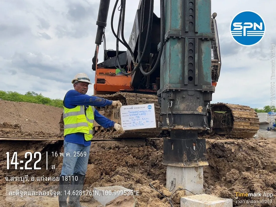
1. The hammer must be brought in and set up — Driven-pile jobs use the hammer of the piling rig already on site, but bored pile sites have no driving equipment. The test team must therefore bring a test hammer with a guide frame and a crane and set them up above the pile head. This takes up space and requires crane access.
2. The hammer must be heavy enough to mobilize capacity — Bored piles usually have larger cross-sections and carry higher loads than driven piles on the same project, so the hammer must be heavy enough to move the pile down slightly with every blow. If the pile does not move at all, the capacity has not been fully mobilized and the result is only a proven minimum, not the true ultimate capacity.
3. The pile head needs more preparation — The top of a bored pile carries a layer of laitance and sediment from the concreting process. It must be trimmed back to sound concrete and the surface made flat and perpendicular. Full details are in the article Pile head preparation before testing
4. Impact cushioning is required — A pile head plate and a cushion such as plywood are placed between the hammer and the pile head to spread the force and lengthen the impact duration so the pile head does not crack. Cushion thickness directly affects the recorded waveform.
For an overview of which test method suits each pile type, read Bored pile vs driven pile: how testing differs
The figure below brings all four aspects together in one picture. Reading from top to bottom: the test hammer in its guide frame, the cushion on the pile head trimmed to sound concrete, and the opposing gauge pairs in the pit excavated around the pile head. The box on the right summarizes how each point differs from driven-pile work.
What are the steps of High Strain testing on a bored pile?
The test has 7 main steps, starting with checking concrete strength and preparing the pile head, followed by attaching gauges and setting up the hammer, and ending with dropping the hammer and analyzing the results with CAPWAP.
- Check concrete age and strength — The pile must be strong enough to take the impact without damage. See the criteria in How many days after casting can a pile be tested?
- Trim and prepare the pile head — Trim back to sound concrete and make the surface flat and perpendicular to the pile axis.
- Expose the pile side — Excavate the soil around the pile head to expose enough pile shaft to fix the gauges below the pile head.
- Install the gauges — Fix strain transducers and accelerometers in opposing pairs around the pile to average out the effect of an eccentric impact.
- Set up the hammer and guide frame — Align the hammer with the pile axis and place the pile head cushion.
- Drop the hammer and record signals — Start from a low drop height and increase it step by step, while monitoring the stress in the pile so it does not exceed a safe level.
- Analyze the results — Make a preliminary assessment on site with the Case Method, then a detailed analysis with CAPWAP in the office.

For how to read the values in the report, see How to read PDA test results
The model below places all 7 steps on a single site. The numbered tags in the figure match the work sequence in the box on the right. Note that the crane needs a place to stand on ground that can carry it, and the signal cables must run from the test pit to the PDA unit — which is where the limitations in the next section come from.
What are the limitations of PDA on bored piles?
There are three main limitations: very large piles may not be fully mobilized, the site needs room for a crane, and the result depends on signal quality.
- Very large piles may not be fully mobilized — The larger the pile and the higher its capacity, the heavier the required hammer, to the point where it may not be cost-effective or the site cannot accommodate it. In that case the result is only a proven minimum capacity.
- Requires space and a crane — Unlike driven piles, which use the existing piling rig, a crane may not be able to set up on a cramped site or soft ground.
- Results depend on signal quality — A poorly prepared pile head, a tilted face or loosely fixed gauges make the signal unusable and require a retest.

If the pile is too large for the hammer to fully mobilize its capacity, the alternative is a Static Load Test, which applies real load to the pile head. It gives the most direct result but takes more time and budget. For details on setting up the reaction system, read Kentledge vs reaction pile: what's the difference?
Many projects therefore combine the two methods: a Static Load Test on a sample pile, with PDA covering the other piles as required by the specification. The pros and cons of each method are compared in Dynamic vs Static Load Test: which to choose?
Can PDA tell you the integrity of a bored pile?
Not directly. Testing capacity and testing integrity are two separate things.
PDA answers the question how much load can the pile carry, but it does not directly answer whether the pile is sound along its full length. For bored piles, which are cast in a hole and cannot be seen during concreting, integrity is just as important as capacity.
Bored pile projects therefore usually run two tests side by side: PDA for capacity, and Seismic Integrity Test or Cross Hole Sonic Logging (CSL) for integrity. CSL gives more detailed results but requires access tubes cast into the pile, so it must be planned in advance.
Comparison table: PDA on bored piles vs driven piles
The standards and analysis principles are the same. What differs is the impact source, pile head preparation, retesting and the main limitations.
← Scroll to see the full table →
| Topic | Driven pile | Bored pile (cast-in-place) |
|---|---|---|
| Reference standards | ASTM D4945 / DPT 1252-51 | ASTM D4945 / DPT 1252-51 (same) |
| Impact source | Hammer of the piling rig already on site | Test hammer must be brought in with a guide frame |
| Pile head preparation | Trim concrete cracked by driving | Trim laitance and sediment, re-square the face |
| Retest (Restrike) | Possible; used to check soil set-up | Not normal practice |
| Main limitation | EOD results may underestimate true capacity | Very large piles may not be fully mobilized |
| Companion integrity test | Seismic Integrity Test | Seismic Integrity Test or CSL |

For more on Restrike and soil set-up in driven piles, read What is a Restrike Test?
How much does PDA testing of a bored pile cost?
SPN's PDA service starts at approximately THB 5,500 per pile. A Static Load Test is approximately THB 50,000-150,000 per pile and up, depending on the test load and reaction system, and a Seismic Integrity Test is approximately THB 100-150 per pile.
This price excludes travel and equipment mobilization costs, which are charged extra depending on the distance to site.
For bored piles, the actual cost also depends on the hammer size required and site access. Send the pile size, length and design load to SPN's engineering team for assessment and receive a free quotation within 24 hours. See the full range of services on the pile testing services page.
This content explains the principles and practice of High Strain testing on bored piles for general understanding. The appropriate hammer weight, the number of piles to test and the acceptance criteria for each project must be set by the responsible engineer and stated directly in that project's specification.