A static load test measures pile bearing capacity directly, because it applies a real load and measures the real settlement. The heart of the setup is the reaction system, which must be designed to carry more than the maximum test load. This article compares both systems for engineers and contractors who need to plan the site work.
Why Does a Static Load Test Need a Reaction System?
A reaction system is the structure that holds the hydraulic jack in place so that the jack can actually push down on the pile head.
A static load test uses a hydraulic jack to push the pile head down with a specified load, but the jack needs a reaction force pushing back from above; otherwise the jack would lift itself instead of pushing the pile down. The reaction system is what braces the jack so it can transfer the load into the test pile.
The reaction system must always be designed to carry more than the maximum test load. The maximum test load is usually set as a proportion of the design load according to the project specification.
The static loading procedure follows ASTM D1143/D1143M-20e1 and DPT 1251 (Department of Public Works and Town & Country Planning), which set out the incremental loading steps, load holding and settlement recording.
The diagram below compares the load paths of both systems. Follow the orange arrows (jack force P), which push the beam up and the pile down at the same time. On the kentledge side, this force is resisted by the dead weight W (blue arrow); on the reaction pile side, it is resisted by the uplift force T in the anchor piles (red arrows).
How Does Kentledge Work and How Much Dead Weight Is Needed?
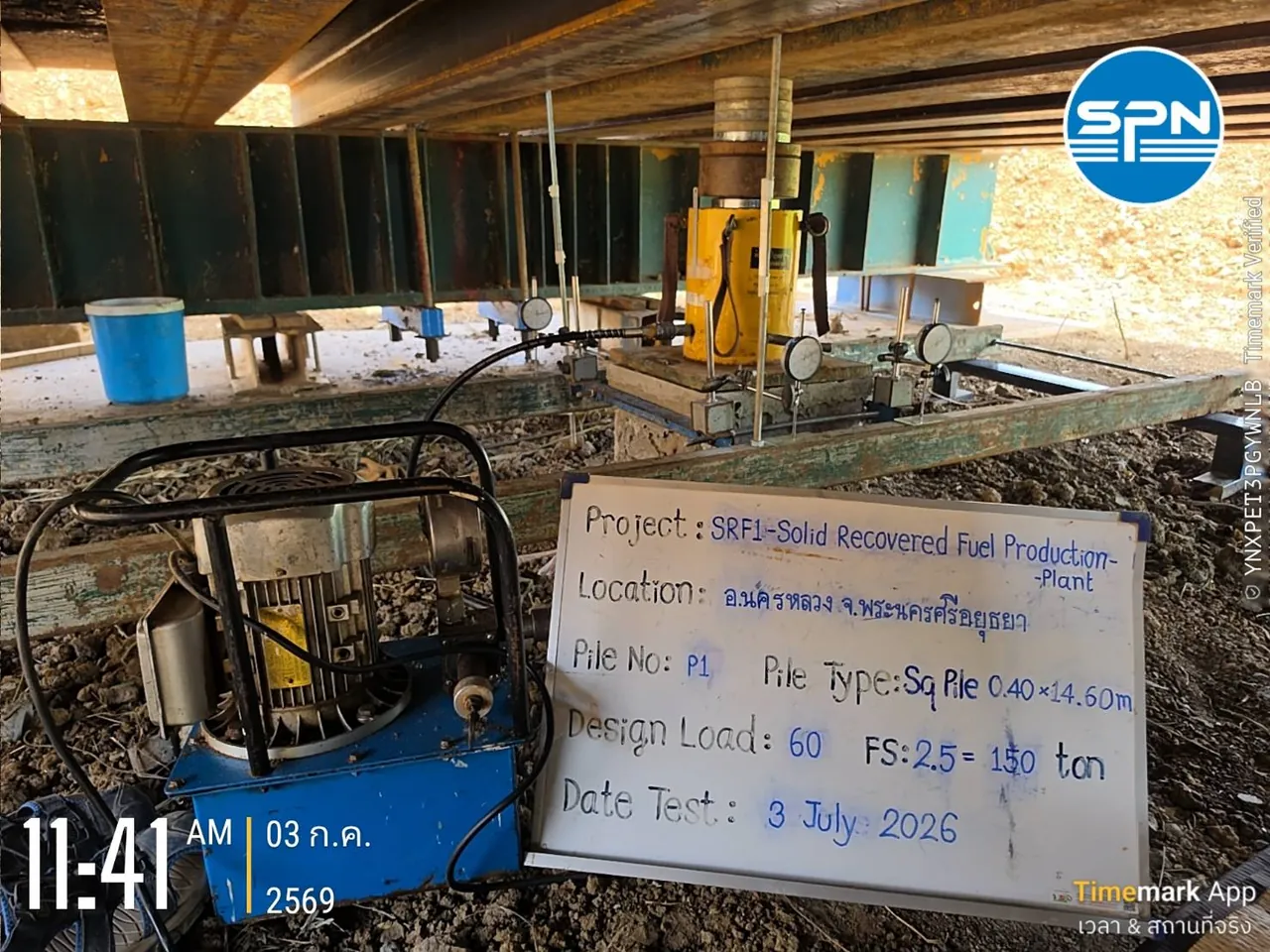
Kentledge is a reaction system that uses real stacked weight, such as concrete blocks, steel or weight plates, placed on a platform straddling the pile head. The total dead weight must always exceed the maximum test load.
When the jack pushes up, the entire stacked weight acts as the reaction, pushing the jack back down onto the test pile. For example, for a test at 200 t, more than 200 t of dead weight must be stacked to provide a safety margin as specified by the design engineer.
The platform rests on supports such as cribbing stacks of timber sleepers, which must sit on ground able to carry the load securely and be placed away from the test pile at the distance set by the project specification, so that the platform weight does not load the soil around the test pile and distort the results.

Advantages of Kentledge
- Straightforward, with no need for additional anchor piles; suitable where there are no surrounding piles to use as anchors
- Suitable when a single pile must be tested without disturbing adjacent piles
- The reaction is constant and predictable, because it is real weight that can be weighed
Limitations of Kentledge
- Large amounts of dead weight must be transported to site; the higher the test load, the more time and transport cost
- Requires a large area for the platform and the stacked weight
- Platform stability is a concern if the ground is soft or the stack is unbalanced; safety must be strictly controlled
- Not suited to very high test loads, because stacking several hundred tonnes is difficult

How Do Reaction Piles Work and How Many Are Needed?
A reaction pile (or anchor pile) system provides the reaction through anchor piles, typically 2–4 piles around the test pile, with a main reaction beam spanning across and connecting the anchor pile heads.
When the jack pushes up, the beam transfers the force to pull the anchor piles upward as uplift. The anchor piles resisting that uplift become the reaction that lets the jack push the test pile down. The number and capacity of the anchor piles must be designed so that their total uplift capacity exceeds the maximum test load.
Anchor piles work in tension on the same principle as a pile uplift (tension) test; their uplift resistance comes mainly from friction between the pile shaft and the surrounding soil.

Advantages of Reaction Piles
- Handles higher test loads better than kentledge, so it is common for large-diameter bored piles
- No need to transport large amounts of dead weight to site
- Uses less site area for the same test load

Limitations of Reaction Piles
- Requires additional anchor piles to be designed and installed, adding cost and time if no existing piles are available
- The spacing between the anchor piles and the test pile must be sufficient to limit interaction that affects the test results
- The reaction beam and anchorage design is more complex and must be calculated by the responsible engineer

What Is the Difference Between Kentledge and Reaction Piles?
Kentledge and reaction piles differ in the source of the reaction: kentledge uses real stacked weight, while reaction piles use the uplift resistance of anchor piles. This difference affects the achievable test load, site area, transport and safety issues, as shown in the table below.
← Scroll to see the full table →
| Topic | Kentledge (dead weight) | Reaction Pile (anchor piles) |
|---|---|---|
| How the reaction is provided | Real weight stacked on a platform | Uplift of anchor piles + reaction beam |
| Suitable test load | Low to medium | Medium to very high |
| Site area | Needs a large area | Less for the same load |
| Transport | Large amount of dead weight | No dead weight to transport |
| Additional piles needed | Not required | Requires 2–4 anchor piles |
| Design complexity | Lower | Higher |
| Main safety issue | Stability of the kentledge platform | Uplift transfer and interaction distance |
Kentledge or Reaction Piles: Which Should You Choose?
Choose reaction piles when the test load is very high, the site is confined, or existing piles can be used as anchors. Kentledge suits open sites with moderate test loads. The decision depends on 3 main factors: test load, site area and availability of anchor piles.
- Test load: if the test load is very high, reaction piles usually have the advantage, because stacking several hundred tonnes of dead weight is difficult.
- Site area: a confined site favors reaction piles, while for an open site with a moderate test load, kentledge is more convenient.
- Availability of anchor piles: if there are existing piles that can serve as anchors, reaction piles are more economical; if there are none at all, stacking weight may be more cost-effective.

The choice of system and the detailed design should be made by the responsible engineer based on the actual project conditions, not fixed from an article. For an overview of the test method, see What Is a Static Pile Load Test?, and if you are still deciding between test methods, see Dynamic vs Static Load Test: Which Should You Choose?
If you choose reaction piles, the site will have the components shown in the 3D view below. Note that the reference beam (G) has its supports outside the anchor pile line, and the front cutaway shows the anchor piles being pulled up (red arrows) and resisted by the soil (green arrows). The right panel is a checklist for selecting the system and before testing.
Once the Setup Is Complete, How Is the Test Run and Read?
Once the reaction system is ready, the load is applied in increments, and the settlement of the pile head is measured at each increment. The results are then plotted as a load-settlement curve to assess bearing capacity against the criterion set in the specification, such as the Davisson offset.
Before loading begins, the pile head must be prepared smooth and level, and the jack set on the pile axis. See details in Pile Head Preparation Before Testing
Detailed guidance on reading the results is in the article How to Read Static Load Test Results
SPN Soil Engineering provides pile testing services, including static load tests, nationwide across all 77 provinces of Thailand. Reports are certified by a licensed civil engineer (Council of Engineers Thailand) and can be submitted to the relevant authorities for building permits.
How Much Does a Static Load Test Cost per Pile?
A static load test costs approximately THB 50,000–150,000+ per pile, depending on the test load and the reaction system chosen, because the main cost lies in preparing the reaction system, not the test itself.
This price does not include travel and equipment mobilization, which are charged extra based on the distance to the site. For figures that match your project, contact us for a free quotation within 24 hours.
This article is provided as general engineering knowledge. The choice of reaction system, number of anchor piles, required dead weight, spacing between anchor piles and the test pile, and safety margin must follow the project's specific requirements and the calculations of a licensed responsible engineer. It is not design advice specific to any particular project.