What is an existing concrete floor inspection, and when is it needed?
An existing concrete floor inspection (existing slab assessment) collects the real data of a floor that is already in place: its thickness, material layers, reinforcement, concrete strength and what is actually supporting it underneath. These values are used to calculate whether the floor can carry the required service load. The outcome is a report that says the floor is “usable”, “usable with limits” or “must be upgraded first”.
Situations where the existing floor should be checked before deciding:
- Renovation or change of use: for example turning a car park or open undercroft into classrooms, offices, shops or storage that need a higher live load.
- Heavy items or machinery: document shelving, safes, storage racks or machines that put point loads on the slab.
- Pouring a topping over the old floor: to level it or in the hope of making it stronger, which immediately adds dead load.
- Cracks, settlement or a hollow sound underfoot: signs that the soil under the slab may have settled and left a void.
- No drawings, or drawings missing key data: many older buildings have no stated concrete strength, steel grade or design live load.
For a whole-building check before an extension, see what structural checks an old building needs before extension or change of use. This article focuses on the floor, the element whose use changes most often.
Does your ground floor rest on soil, or span between beams?
The first question to answer before assessing strength is where the floor sends its load, because the two systems work completely differently. A slab on ground passes load straight into the soil, so the slab itself carries little bending. A suspended slab must carry all of the bending itself and pass the load to beams and piles.
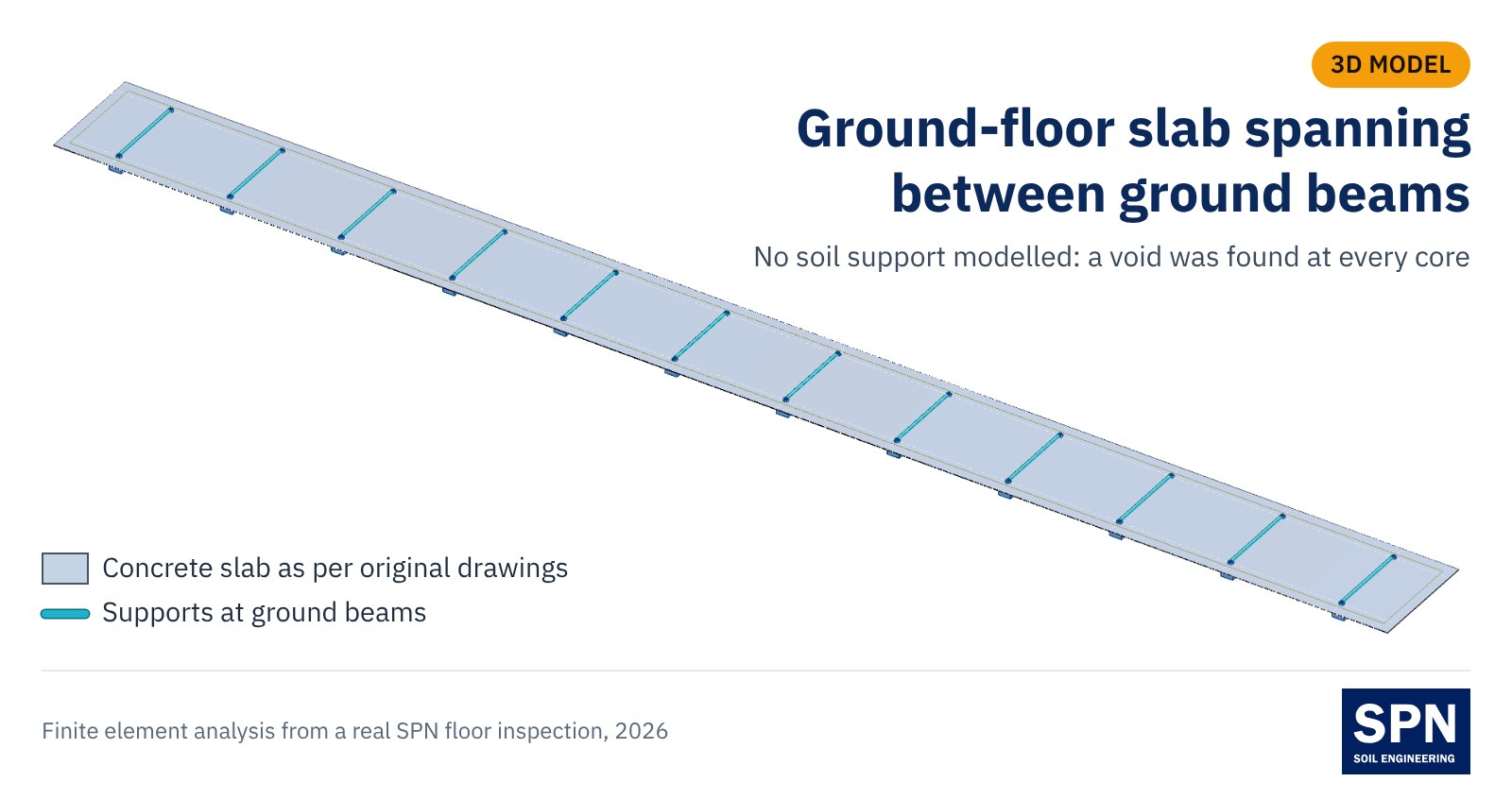
A common problem in the soft clay of Bangkok and its surroundings is a ground-floor slab designed to rest on soil while the building stands on piles. Over time the soil under the slab settles while the beams and piles do not. The slab gradually ends up “floating” above the soil and has to span between ground beams, a job it was never designed for. More on settling fill in how to deal with settling fill.
What are the steps of an existing concrete floor inspection?
An inspection that gives a usable answer has six steps. Each answers a different question, and the data from every step is used together in the final calculation.
← Scroll to see the full table →
| Step | Method / reference standard | Data obtained |
|---|---|---|
| 1. Review existing records | Construction drawings, calculations, renovation history (if available) | Floor system, beam spans, design thickness and reinforcement |
| 2. Condition and crack survey | Visual inspection, crack width with a crack gauge, crack map | Location, pattern and width of cracks |
| 3. Concrete coring | Concrete coring per ASTM C42/C42M | Actual thickness, layering, voids under the slab, reinforcement |
| 4. Concrete strength testing | Core compressive strength per ASTM C39/C39M + rebound hammer per ASTM C805/C805M | Actual strength of each material layer |
| 5. Soil under the slab | Kunzelstab (KPT) and hand auger through the core hole + laboratory soil tests | Soil type, density, approximate bearing capacity |
| 6. Calculation with a model | 3D finite element model, strength checks to a design code such as ACI 318 | Bending moments, required reinforcement, deflection |
1. Review existing records: drawings are only a starting point
Original drawings show how the floor was designed, but not its current condition. Older buildings have often had toppings added, finishes replaced or local repairs over the years, and many old drawings do not state concrete strength, steel grade or design live load. Values from drawings must always be confirmed on site.
2. Condition and crack survey (crack mapping)
A crack survey records the location, direction and width of every crack on a plan and photographs each one against a tape or crack gauge. Crack patterns point to the mechanism: straight cracks crossing in a grid on a screed often relate to shrinkage or settlement of the soil below, while cracks running parallel to the beams, whether on the top surface over a beam or on the soffit at mid-span, indicate bending. For more detail see which structural cracks are dangerous, and for the full 23-point crack map and site photos from this job see how to survey concrete floor cracks.
3. Concrete coring: the step that shows what is under the floor
Concrete coring uses a diamond core bit to cut a sample through the full slab thickness, per ASTM C42/C42M. It is the most important step for an existing floor because it gives four answers at once: actual thickness, the sequence of screed and concrete layers, whether reinforcement is present, and any void under the slab, which cannot be seen from above. Once the core is through, the gap from the slab underside to the soil can be measured directly. Read more in what a concrete core test is.


4. Concrete strength: cores are more reliable than a rebound hammer
The strength of existing concrete is found by testing the cores in the laboratory per ASTM C39/C39M, corrected for length-to-diameter ratio per ASTM C42/C42M. Existing floors often have several layers, so results for the structural concrete must be kept separate from those of the screed toppings and never averaged together.
A rebound hammer (ASTM C805/C805M) is quick and non-destructive but only measures surface hardness. It is useful as supporting data or to compare uniformity between points, not as a replacement for cores. In the case study below, rebound readings were clearly higher than the core results. See the limits in what a rebound hammer test is.
5. Soil under the slab: is it still supporting the floor?
Once a core is through, the same hole can be used to check the soil without breaking out more floor. A common method is the Kunzelstab Penetration Test (KPT), which counts the blows needed to drive a cone 20 cm at a time to show soil density with depth, together with a hand auger to sample the soil for USCS classification (ASTM D2487), moisture content and Atterberg limits. These data show whether the soil can still help carry the floor and, if the floor is to be rebuilt as a slab on ground, how much ground improvement is needed.
6. Calculation with a 3D model: putting all the data together
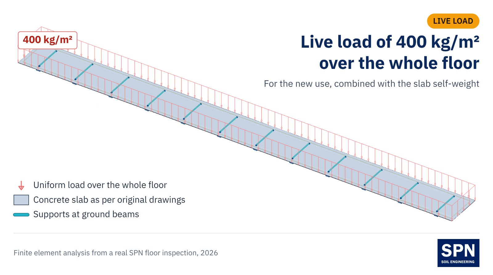
The last step is a finite element model of the slab in structural analysis software, using the thickness, concrete strength, reinforcement and supports actually found on site. Dead load and the new live load are applied, and the model gives bending moments, required reinforcement and deflection, which are checked against the design code limits.
The advantage of a 3D model is that the behaviour of the whole floor is visible in one picture: which bays deflect most and where negative moment occurs over the beams. It also helps owners understand the result far more easily than tables of numbers. The full calculation report should be prepared and signed by an engineer; see what a structural calculation report contains.
Case study: what did an inspection of an old 5-storey building's ground floor in Bangkok find?
This is a real SPN job from 2026 (the building and its original drawings are not disclosed). The ground floor of an old 5-storey building in Bangkok had been an open undercroft, and the owner wanted to convert it into usable space with a live load of 400 kg/m², and asked whether more concrete should be poured over the existing floor. The SPN team spent 3 days on site. The scope was:
How did the site findings differ from the original drawings?
← Scroll to see the full table →
| Item | Original drawings | Found on site |
|---|---|---|
| Floor thickness | 0.08 m | Upper layer 0.19–0.37 m (average 0.27 m), 2 to 4 layers of screed and concrete |
| Reinforcement | Small plain round bars @0.15 m | No reinforcement found in any of the 13 cores |
| Support below the slab | Section shows soil under the slab | Void at every core, 0.05–0.45 m high |
| Concrete strength (cylinder) | Not stated | Concrete layers 105–335 ksc (average 197 ksc), screed toppings 34–218 ksc |
| Soil under the slab | Not stated | Weakest layer roughly 1.1–2.3 t/m² bearing capacity |
| Cracks | — | Found in all 12 bays surveyed, mostly wider than 2 mm |

These findings changed the whole question. What everyone assumed was a thick concrete floor resting on soil was in fact the original thin slab buried under several rounds of screed and concrete, with no reinforcement in the toppings, and with the soil below already settled away from its underside. The rebound hammer also gave roughly 164–463 ksc, clearly higher than the cores. Relying on rebound readings alone would have overestimated the floor's strength.

What did the 3D model calculation show?
With the soil no longer touching the slab, the engineer analysed the slab spanning 12.00 m between ground beams without any soil support, using the thickness and reinforcement from the original drawings, an average concrete strength of 197 ksc, and strength checks to ACI 318M-14 (strength design method). The results:
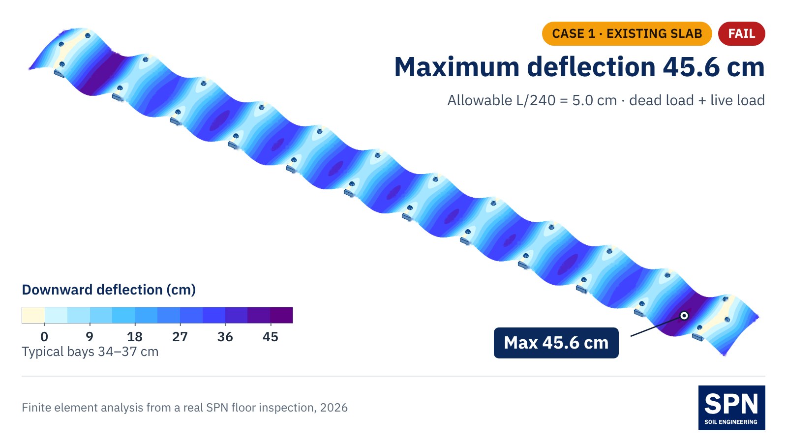
- Case 1, existing floor: maximum deflection 45.6 cm (the first image in this article), above the L/240 limit of 5.0 cm, and the existing reinforcement was insufficient for bending in many areas → Fail
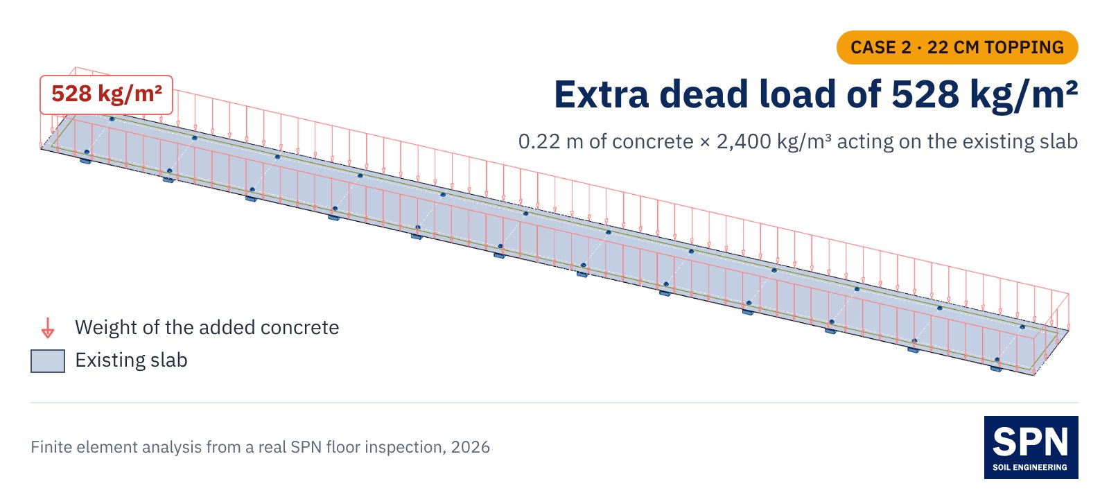
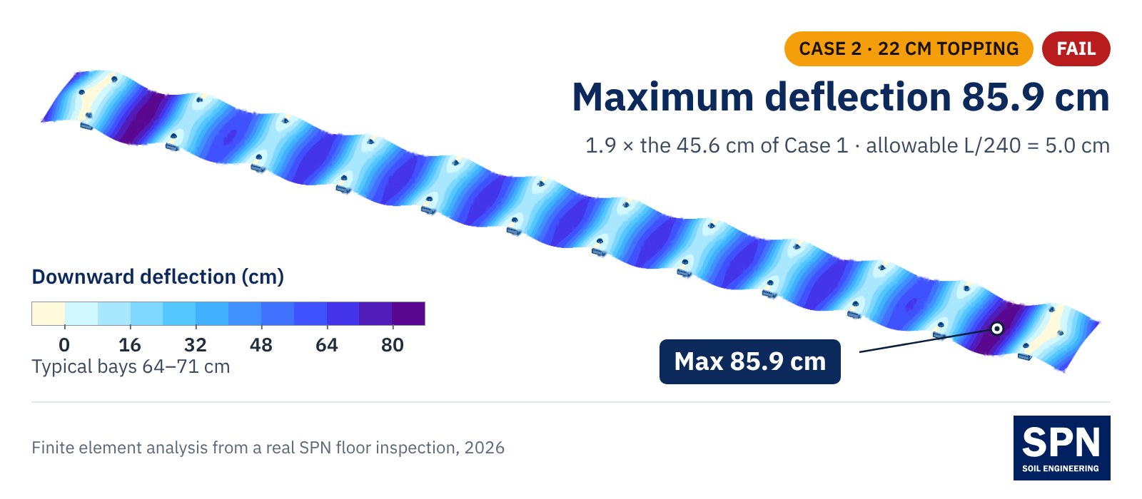
- Case 2, 22 cm concrete topping added: 528 kg/m² of extra dead load; deflection rose to 85.9 cm and the reinforcement was still insufficient → Fail
The 45.6 and 85.9 cm values come from the model under assumptions that ignore the soil and do not count the toppings as carrying bending. They show that the floor structure as originally designed does not have enough capacity for the new use; they are not how far the real floor has already sagged. In reality some soil contact and the toppings still help, but neither can be relied on in design because the soil can keep settling and the toppings are unreinforced. On the other hand, the model used the reinforcement shown on the original drawings and the average strength of 197 ksc, both more favourable than the real floor (no reinforcement was found in any core, and the lowest result for the concrete layers was 105 ksc), and Case 1 left out the weight of the existing toppings. Using the as-found values would only make the result worse, so the conclusion does not change.
Does pouring a thicker concrete topping over the old floor make it stronger?
Not necessarily, and in many cases it makes things worse. A topping immediately adds dead load: 22 cm of concrete weighs about 528 kg/m², more than the 400 kg/m² live load the owner wanted to use. If the new concrete is not designed to work with the old slab (for example, with no reinforcement and no dowels tying the layers together), all of the added weight falls on the existing slab and beams.
Another point that is often missed is that the extra weight does not stop at the floor. In the case study the original 0.08 m slab weighed about 190 kg/m², but the present floor with all its toppings weighs 460–890 kg/m². That load goes on into the beams, footings and piles, which must be checked separately before any more weight is added.
If the floor fails, what are the options?
The right option depends on each building's findings, and the details must be set by the structural design engineer. Common approaches when a floor is found to be unsupported with too little reinforcement:
← Scroll to see the full table →
| Approach | Principle | Points to know |
|---|---|---|
| New structural slab independent of the soil | Remove the old floor and build a new reinforced concrete slab designed to carry load to the beams and piles | Unaffected by future soil settlement; existing beams and piles must be checked too |
| Slab on ground after ground improvement | Remove the old floor, dig out loose soil, place and compact selected fill in layers, verify with a field density test, then cast a new slab | On soft clay long-term settlement is still possible; see ground improvement methods |
| Void filling / grouting | Inject material to fill the gap so the soil touches the slab again | Does not add bending capacity to a slab with too little reinforcement, so it should not be the only measure |
| Interim measures | Avoid heavy or concentrated loads such as document shelving, safes or machinery | Monitor cracks and settlement regularly; if they grow, stop using that area |
Existing floor inspection vs floor load test: which should you choose?
The inspection described here answers “what is the floor made of, what supports it and what can it carry by calculation”. A floor load test places real load on the floor and measures deflection and recovery per ACI 318-19 Chapter 27, which is the most direct proof that the floor can carry the tested load.
← Scroll to see the full table →
| Aspect | Floor inspection + calculation | Floor load test |
|---|---|---|
| Question answered | What the floor is like and why it can or cannot carry the load | Whether the floor actually carries the tested load |
| Coverage | The whole floor, through a model built on data from the test points | Only the bays tested |
| Best when | No drawings, suspected voids or settlement, upgrade options needed | Floor data is complete and proof is needed before use |
| Caution | Results depend on the model assumptions | Floors with voids or heavy cracking should be inspected before deciding to load test |
For an existing floor with suspected voids or no drawings, the recommended order is to inspect and calculate first, then consider a floor load test to confirm only the critical bays. For factory or warehouse floors carrying racks and forklifts, read how much load a factory or warehouse floor can carry. To locate reinforcement before coring, GPR concrete scanning helps choose the core positions.
How long does an existing floor inspection take and what does it cost?
Time and cost depend on floor area, number of cores, soil tests and model complexity. In the case study above, fieldwork for 13 cores took 3 days, followed by laboratory testing, analysis and a report certified by a licensed civil engineer (Council of Engineers Thailand) with signature and registration number.
SPN prices each building on its actual scope. Send a plan or site photos via LINE @spnth or request a free quote within 24 hours. Prices exclude travel and equipment mobilisation, which are charged by distance to site. See all structural testing services on our non-destructive testing and structural inspection page.
Summary
An existing concrete floor that looks sound from above can hide a void underneath, unreinforced toppings and lower concrete strength than expected. A reliable inspection therefore cores into the real floor, tests strength on cores, checks the soil below, and puts all of the data into a 3D structural model.
The key lesson from the case study is that “pour a thicker topping” is not an automatic answer. On a slab spanning between beams with little reinforcement, the topping nearly doubled the deflection. Before renovating, changing use or placing heavy items on an existing floor, have an engineer inspect it and issue a report first.