Why Carry Out a Floor Load Test?
It is done when calculation alone cannot show whether an existing floor can carry a new load. In renovation work or new machinery installation, the most common question is "Can the existing floor carry the machinery or the new use?" But the data needed for calculation is often incomplete, for example:
- No original construction (as-built) drawings, or incomplete drawings
- The actual concrete strength and amount of reinforcement are unknown
- The building is old, and materials may have deteriorated from their design condition
- The new use imposes more load than the original design
When there are many unknowns, analytical evaluation alone may not be enough. A Load Test tests the real structure under real conditions, so the result already reflects the materials, construction quality and deterioration. If you are not sure what floor system you have or where to start checking, read the overview at how much load can a factory floor carry
In practice it is often done together with a Concrete Core Test (concrete coring per ASTM C42 / C39): the Core Test confirms material quality, while the Load Test confirms the behavior of the whole slab. Both methods are part of structural inspection (NDE)
Which Standard Does a Floor Load Test Follow?
It follows ACI 318-19 Chapter 27, Strength Evaluation of Existing Structures by load test, which divides the test into 2 methods:
← Scroll to see the full table →
| Test method | Characteristics | Best for |
|---|---|---|
| Monotonic Load Test (27.5) | Load is increased in one direction up to the maximum, then held ≥ 24 hrs | Where shear failure or development of reinforcement is a concern — the sustained load allows cracking/creep to show |
| Cyclic Load Test (27.6, per ACI 437.2) | Load is applied and removed in cycles at increasing levels | When you need to check linear-elastic behavior and the permanency of deflection in each cycle |
For typical factory floors, the Monotonic method with water ponding is the most popular, because water gives a uniform load that is easy to control, safe, and can be calculated directly from the water level: 10 cm of water equals 100 kg/m²
The structure to be tested must be at least 56 days old, unless the owner, contractor and design engineer jointly agree to test earlier.
How Is the Total Test Load (Tt) Calculated?
Use the largest value from the 3 equations in ACI 318-19 Section 27.4.6.2; the total test load Tt includes the self-weight of the existing floor.
(b) Tt = 1.0Dw + 1.1Ds + 1.0L + 1.6(Lr or S or R)
(c) Tt = 1.3(Dw + Ds) Dw = dead load (slab self-weight) · Ds = superimposed dead load · L = live load
Worked example — RC slab 120 mm thick, service live load L = 300 kg/m²
← Scroll to see the full table →
| Item | Value | Source |
|---|---|---|
| Dead load Dw | 288 kg/m² | 0.12 m × 2,400 kg/m³ |
| Tt (governing eq. a) | 768 kg/m² | 1.0(288) + 1.6(300) |
| Load actually applied | 480 kg/m² | Tt − Dw (the slab already carries itself) |
| Converted to water depth | 48 cm | 480 ÷ 1,000 kg/m³ |
Load actually applied = Tt − load already on the floor, not the full Tt, because the slab itself already counts as part of the test load. The value of L and the load items used in the calculation must be set by the responsible engineer for each project.
How Is a Monotonic Water Ponding Test Carried Out?
The test has 5 steps, from preparing the water bund to measuring recovery. Site time is typically 2–3 days per test location.
1. Prepare the water bund
Build the bund with plywood walls braced by scaffolding or steel joists to resist water pressure, lined with a waterproof membrane. The bund should cover the critical region of the slab panel to be tested. If water ponding is not possible on site, for example on an upper floor or where there is no drainage, see alternatives and how to arrange the load so results are not distorted at Floor Load Test loading methods: water ponding vs IBC tanks vs sandbags
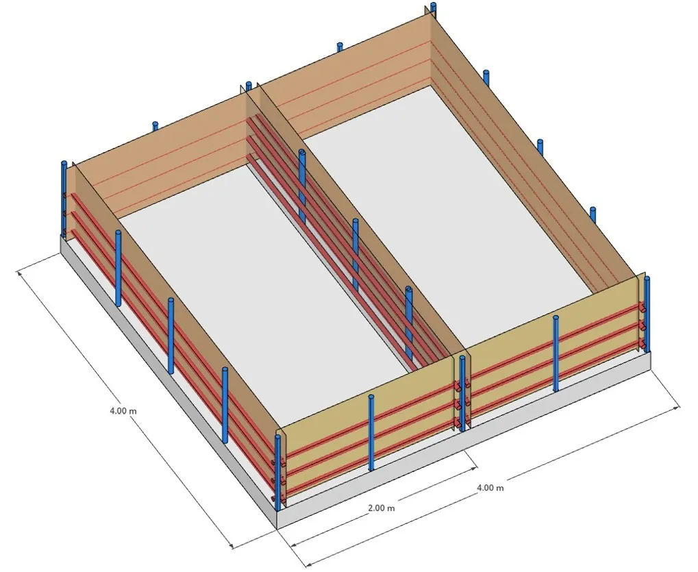
The load must be arranged to produce the maximum load effect in the critical region. For a single-span slab, the critical point is the midspan moment, so a patch load centered on the span gives a result very close to loading the full span (in the case study below, a 4.0 m patch on a 4.75 m clear span gives ~97.5% of the full-load midspan moment).
2. Install the instruments
- Deflection gauges (dial gauges) under the slab soffit at no fewer than 3 points, with midspan as the critical point
- Gauge stands must be independent of the structure carrying the test load, otherwise readings will be distorted
- Take the datum (zero reference) reading no more than 1 hr before applying the first load increment (27.5.2.2)
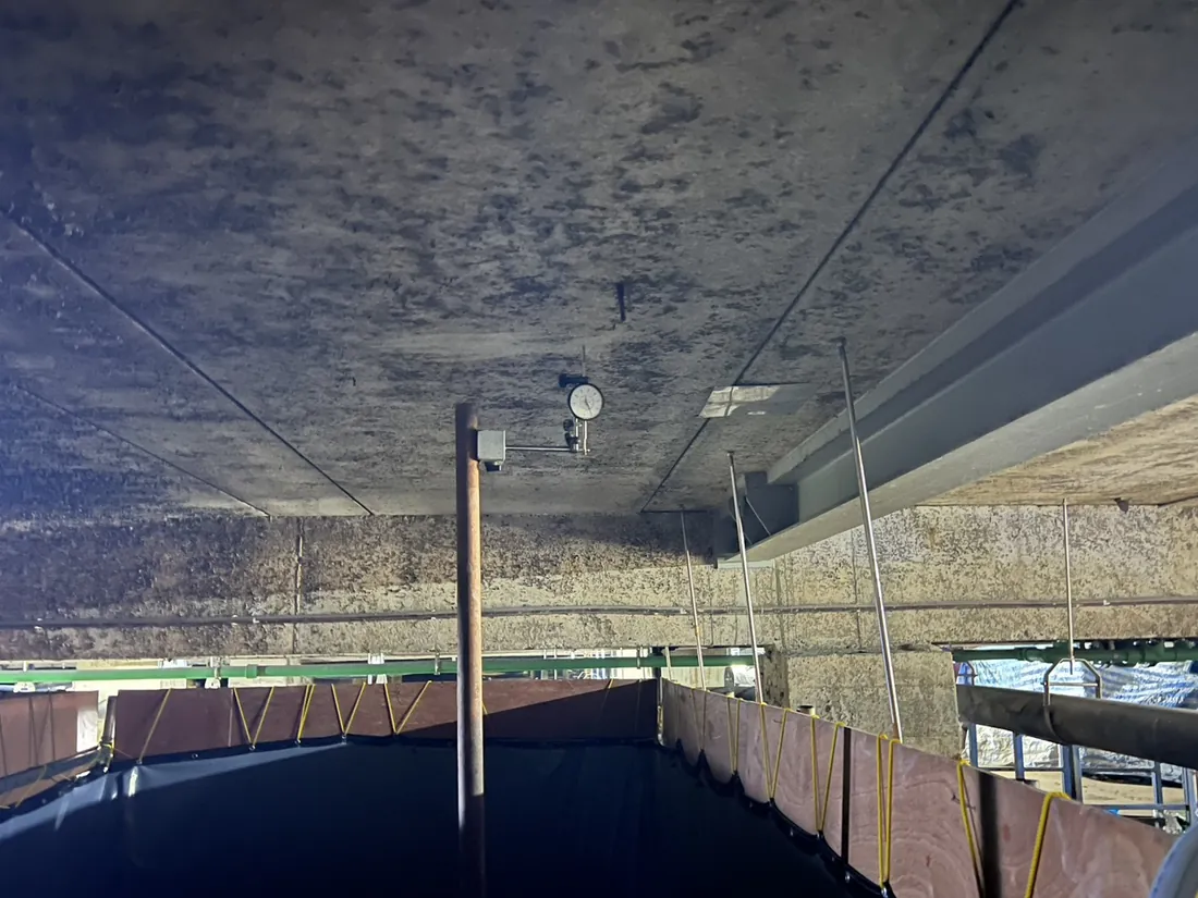
The 3D view below cuts the slab panel in half so both sides can be seen at once: on top is the water bund straddling midspan, and below are the dial gauges on stands set up from the floor below, not touching the slab under test.
3. Apply the load in increments
Per 27.5.1.1, the load must be applied in at least 4 roughly equal increments, for example water at 12 / 24 / 36 / 48 cm (25% of the test load each). At each increment, wait for readings to stabilize, record every deflection gauge and visually inspect for cracks.
4. Hold the full load for 24 hours
Once the full load is reached, hold it for no less than 24 hrs (27.5.1.3). Record readings at +30 min, +60 min, then every 1 hr, along with the temperature and actual water level.
5. Remove the load and measure recovery
After 24 hrs, remove the load promptly (27.5.1.4), then measure the residual deflection 24 hrs after load removal (27.5.2.4), unless the exception in 27.5.3.6 applies (see the acceptance criteria section).
What Are the Pass/Fail Criteria for a Load Test? (27.5.3)
The floor passes when no damage is found during the test and the deflection meets Section 27.5.3.5 or 27.5.3.6, where Δl is the maximum deflection and Δr is the residual deflection after load removal.
← Scroll to see the full table →
| No. | Criteria | Meaning |
|---|---|---|
| 27.5.3.1 | No spalling / crushing of concrete | Visual inspection throughout the test |
| 27.5.3.2 | No cracks indicating impending shear failure | Diagonal cracks that keep lengthening + widening = danger sign |
| 27.5.3.5 | Δr ≤ Δl / 4 | Residual deflection must not exceed 1/4 of the maximum deflection |
| 27.5.3.6 | If Δl ≤ the greater of 0.05 in. or ℓt²/(20,000h) | 27.5.3.5 can be waived outright, because the structure is so stiff that recovery cannot be distinguished from field measurement error |
If the criteria are not met, a retest is still allowed under 27.5.3.7, starting no sooner than 72 hrs after the first load removal and using the criterion Δr ≤ Δ2/5 (27.5.3.8). The diagram below brings the 5-step loading sequence and the decision path together in one image.
Case Study: Factory Basement Floor, Lat Krabang District
A factory in Lat Krabang District wanted to install utility systems for an injection machine on its existing 120 mm RC basement floor slab. SPN was engaged to evaluate it with a Core Test and a Floor Load Test.
Core Test results: compressive strength of 2 concrete cores ≈ 212–214 ksc (≈ 21 MPa), consistent quality, within a good range.
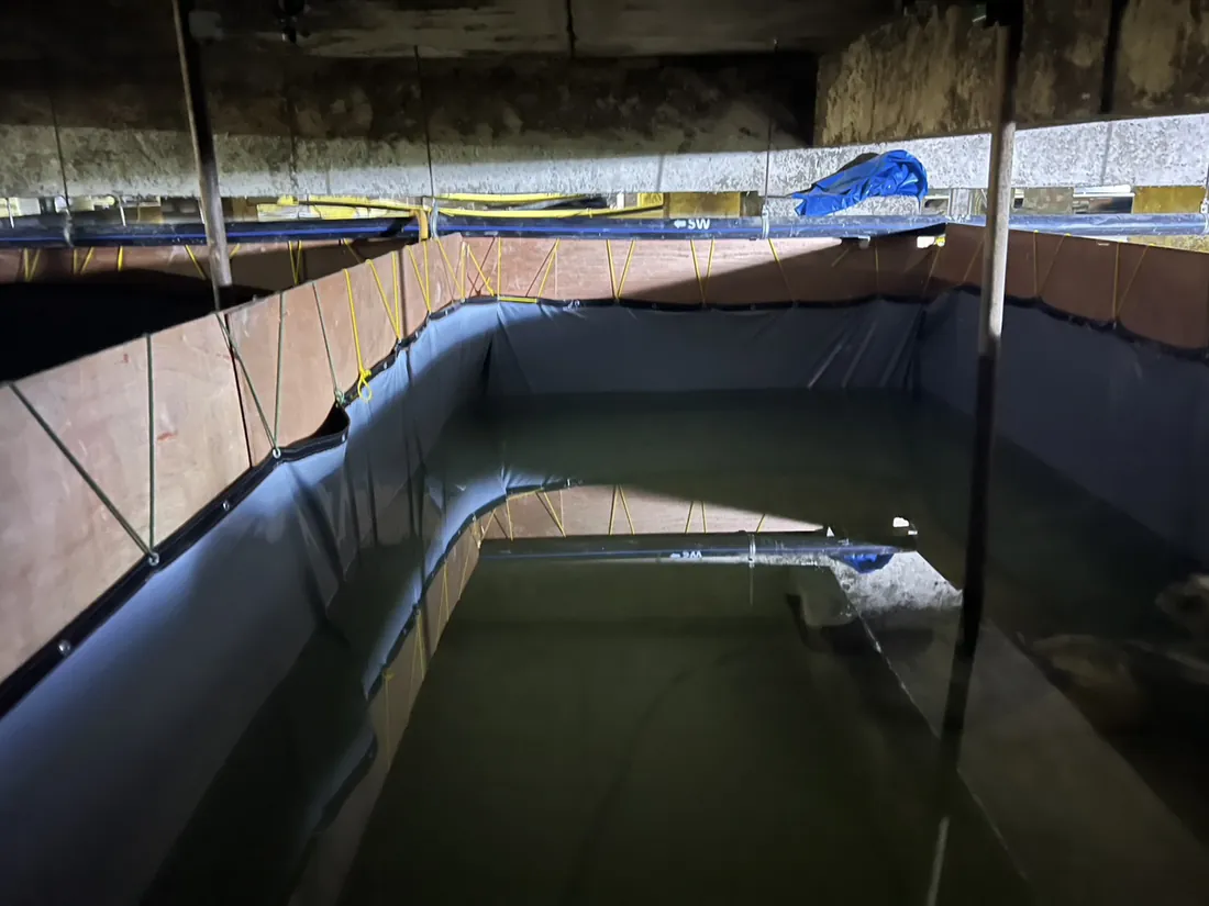
Floor Load Test: test load Tt = 768 kg/m² (governed by 1.0Dw + 1.6L, L = 300 kg/m²), water ponded in a 4.0 × 4.0 m bund to a maximum of 48 cm, applied in 4 increments, full load held 24 hrs, with 3 dial gauges under the slab soffit.
← Scroll to see the full table →
| Item | Value |
|---|---|
| Max midspan deflection Δl | 1.53 mm (at full load +24 hrs) |
| Criterion 27.5.3.6 = ℓt²/(20,000h) = 4,750²/(20,000×120) | 9.40 mm |
| Result | 1.53 ≤ 9.40 mm → pass (recovery measurement can be waived) |
The deflection behavior is also telling: from +6 to +24 hrs the value increased by only ~0.16 mm, showing that deflection had stabilized. Behavior was mainly elastic with limited creep, and no cracks were found throughout the test (Δl ≈ ℓ/3,100, very small compared with the common limit of ℓ/360).
The floor has sufficient capacity to carry a live load of 300 kg/m² for the planned machinery installation.
See another case study with readings at every increment and a deflection–time graph at Case Study: Floor Load Test of a building floor before alteration, Thung Khru District
Summary
A Floor Load Test to ACI 318-19 Chapter 27 proves the strength of an actual structural floor with real load, and suits buildings without original drawings or undergoing a change of use. The essentials are calculating the test load Tt correctly, applying load in at least 4 increments, holding full load for 24 hours, and comparing deflection with the 27.5.3 criteria. Testing the bearing capacity of the "soil" beneath a slab-on-ground is a different test; use a Plate Bearing Test instead.
SPN Soil Engineering provides Floor Load Tests together with Core Tests nationwide, with complete reports including deflection graphs and photos. Reports are certified by a civil engineer licensed by the Council of Engineers Thailand (COE), with signature and registration number. Contact us for a free quotation within 24 hrs.