The method is typically used when cube/cylinder results are missing or questionable, or when NDT gives signals that need confirming. It is also used to build calibration curves for the rebound hammer and UPV. This article explains the procedure, the L/D ratio correction and the precautions.
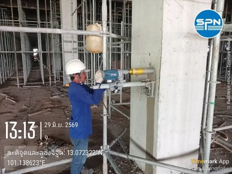
SPN technician using a diamond core drill to take concrete cores from a structural column for compressive strength testing
The SPN team uses a diamond core drill to take concrete cores from a structural column — project in Si Racha, Chon Buri (photo: SPN Soil Engineering)

How is a Concrete Core Test carried out?

A Concrete Core Test has 5 main steps per ASTM C42, from selecting the drilling locations to correcting the values and reporting the results.

  1. Select drilling locations that represent the area being inspected, and avoid the reinforcement using GPR or a Cover Meter
  2. Drill cylindrical concrete cores with a water-cooled diamond core drill
  3. Measure the dimensions, trim the ends and make the end faces flat and square (capping/grinding)
  4. Test the cores for compressive strength per ASTM C39
  5. Correct for the length-to-diameter ratio (L/D) and other factors before reporting the results
3D model of core drilling on a concrete column: marking the rebar lines, fixing a water-cooled diamond core rig, labeling the cores with ID tags and patching the holes (conceptual illustration) A conceptual isometric view of a wide concrete column standing on a floor, labeled 1 to 4. Number 1 is an orange dashed line on the column face showing the scanned and marked reinforcement lines, with the drilling point between them. Number 2 is a core drill rig fixed to the column face, with an orange motor driving a diamond core barrel horizontally into the column, a water line from a cooling-water tank on the floor, and a technician operating the machine. Number 3 is three cores on a tray beside the column, each with an ID tag. Number 4 is a previous core hole higher on the column face that has been patched. The right-hand panel lists five steps: scan for rebar and select the drilling point; drill with a diamond core barrel with the rig firmly fixed and water cooling; collect the cores and tag them with project, location and drilling date; patch the holes with a suitable repair material; and send them to the laboratory for end trimming, compression testing and L/D correction. The engineer decides the number and locations of the cores. 3D model: core drilling on a concrete column Not to scale 1 2 3 4 RC column (horizontal coring) Water tank Cooling Cores + ID tags Core drilling sequence 1 Scan rebar, pick points GPR / Cover Meter · avoid rebar 2 Diamond core drilling Rig fixed firmly, water-cooled 3 Collect & tag cores Project · location · date drilled 4 Patch core holes With suitable repair mortar 5 Send to the laboratory Trim, crush, L/D correction Engineer sets points Representative of the test area Conceptual, not actual layout 1 Avoid rebar lines No steel in the core 2 Rigid rig, drill square Water flow throughout 3 Every core has an ID Fully traceable
Conceptual 3D view: rebar lines marked on the column face, a water-cooled diamond core rig fixed in place, cores collected with ID tags, then the core holes patched
Concrete cores drilled from an actual structure, placed beside a label giving the project and drilling location, before compressive strength testing
Actual concrete cores with a label giving the project, location (beam 3-4/G) and drilling date, before end trimming and compression testing per ASTM C39 (photo: SPN Soil Engineering)

Why is an L/D correction needed?

An L/D correction is needed because the measured compressive strength depends on the core's length-to-diameter ratio (L/D). Shorter cores give a slightly higher strength than the true value because of friction at the platens, so the standard specifies correction factors by L/D ratio to make results comparable. ASTM C42 gives correction factors of 0.98, 0.96, 0.93 and 0.87 for L/D of 1.75, 1.50, 1.25 and 1.00 respectively.

2D section of the Concrete Core Test procedure: drilling cores with a diamond core barrel per ASTM C42, preparing specimens, compression testing per ASTM C39 and L/D correction factors A conceptual diagram in three panels. The first panel is a section through a reinforced concrete slab during drilling: the core drill is fixed to a base and mast, a motor drives a diamond core barrel down between two reinforcing bars, there is a cooling-water line, and a note that the reinforcement must be avoided by scanning with GPR or a Cover Meter before drilling. The second panel shows cylindrical concrete cores with trimmed ends and flat, square end faces, with dimension lines for length L and diameter D. The left core has an L/D of about 2, the reference ratio; the right core is short with an L/D of 1, so its measured value is slightly higher than the true value and must be multiplied by a correction factor. The third panel is a compression testing machine with the core between the upper and lower platens, a load arrow P and a load gauge; compressive strength equals the maximum load divided by the cross-sectional area. The strip below shows the L/D correction factors per ASTM C42: 1.75 × 0.98, 1.50 × 0.96, 1.25 × 0.93 and 1.00 × 0.87. The bottom strip summarizes five steps: select points and avoid rebar, drill the core, trim the ends, compression test, and L/D correction before reporting. Concrete Core Test: drill → prepare → crush → L/D correction Not to scale 1 Drill concrete cores Diamond core drill · ASTM C42 Cooling water Avoid rebar lines Scan with GPR / Cover Meter first Base + mast 2 Prepare specimens Trim ends, make end faces flat & square L D L/D ≈ 2 Reference ratio L/D = 1 Apply correction Short core reads slightly high Measure actual L & D of each core Orange band = capped end (capping) 3 Compression test Laboratory · ASTM C39 P Strength = max. load ÷ area Then correct for L/D before reporting L/D correction factors Per ASTM C42 · values between are interpolated L/D 1.75 × 0.98 L/D 1.50 × 0.96 L/D 1.25 × 0.93 L/D 1.00 × 0.87 1 Select points Avoid rebar 2 Drill core Diamond barrel 3 Trim ends Capping / grind 4 Crush test ASTM C39 5 L/D correction then report
From drilling to testing: cores must have their ends trimmed and faces prepared before testing per ASTM C39; short cores with L/D of 1.75 or less must be multiplied by a correction factor per ASTM C42

Besides L/D, other factors must be considered, such as core diameter, drilling direction relative to the casting direction, and any reinforcement in the core, which the engineer and laboratory take into account when interpreting the results.

When is a Concrete Core Test used?

It is used when the compressive strength of concrete in the actual structure is needed, which other methods can only estimate. Common cases include:

  • Cube/cylinder results that are missing, damaged or questionable
  • NDT such as the rebound hammer or UPV giving signals that need confirming with actual compressive strength
  • Assessing the concrete of an existing structure before an extension or change of use
  • Checking concrete after damage, such as a fire
  • Building project-specific calibration curves for the rebound hammer / UPV

How does a Core Test compare with NDT?

A Core Test gives the actual compressive strength but only at the drilled points, while NDT covers a wide area quickly but gives estimated values.

← Scroll to see the full table →

TopicConcrete Core TestNDT (Rebound/UPV)
Compressive strength resultActual value, most accurateEstimated value
DestructiveSemi-destructive (drilled holes)Non-destructive
VelocitySlow (wait for lab)Fast
Area coverageDrilled points onlyWide
StandardASTM C42 / C39ASTM C805 / C597

The common approach is to use NDT to survey a wide area and find suspect zones, then drill cores only at selected points to confirm and calibrate. This gives both coverage and accuracy with the least destructive drilling. Read more on choosing between the two in NDT vs Core Test: which to choose.

What precautions apply to a Concrete Core Test?

There are 3 main precautions: the core holes, the reinforcement and the interpretation. Drilling leaves holes that must be patched with a suitable material, and the reinforcement should be avoided so as not to affect the structural strength and not to leave steel in the core, which makes interpretation difficult. The number and location of the cores should be set by the engineer to be properly representative of the area inspected. Interpreting the compressive strength of in-place concrete must follow engineering principles; it is not compared directly with the design strength without adjustment. If the results come out below the design value, read the next steps in What to do when concrete strength fails.

Examples of SPN's concrete coring work on actual sites, from setting up scaffolding to reach the drilling points and drilling with a diamond core rig, to the holes left after sampling and the cores ready to send for compressive strength testing.

SPN team setting up scaffolding to reach a core drilling point under a concrete slab soffit
Scaffolding set up to reach drilling points under the slab soffit
Horizontal concrete coring of a column with a diamond core drill
Coring a column with a diamond core drill
SPN technician operating a core drill on a concrete column on site
SPN technician operating the core drill
Core hole in a concrete column after sampling, with a data label and barrier tape
Core hole in a column after sampling (awaiting patching)
Drilled concrete cores with a label giving the project and location, before compressive strength testing
Cores with data labels before sending to the lab
SPN technician coring a building slab with a water-cooled diamond core drill
Coring a building slab with a water-cooled diamond core barrel
SPN team mounting a core drill above the ceiling to sample concrete in a hard-to-reach spot
Coring in a hard-to-reach spot above the ceiling

SPN Soil Engineering provides concrete core testing and full-service non-destructive structural evaluation (NDE). Reports are certified by a civil engineer licensed by the Council of Engineers Thailand (COE), with signature and registration number. Contact us for a free quotation within 24 hours.