
What Live Load Does Thai Law Require for Floors?
The law sets the minimum live load for industrial factory and warehouse floors at 500 kg/m². Live load is the weight of people, goods and movable machinery that the floor must carry, in addition to the self-weight of the structure itself.
The Ministerial Regulation on Structural Design of Buildings and the Characteristics and Properties of Materials Used in Building Structures B.E. 2566 (2023) sets the minimum design values by type of floor use. It repeals Ministerial Regulation No. 6 (B.E. 2527 / 1984), which had long been the usual reference.
← Scroll to see the full table →
| Type of floor use | Minimum live load (kg/m²) |
|---|---|
| Industrial factory areas | 500 |
| Storage areas / warehouses | 500 |
| Commercial buildings, wholesale areas | 500 |
| Commercial buildings, retail areas | 400 |
| Offices (general work areas) | 250 |
| Offices — document and parcel storage rooms | 500 |
| Library stack rooms | 600 |
| Connecting walkways between buildings | 500 |
| Parking for passenger cars (up to 7 seats) and motorcycles | 300 |
| Parking for empty trucks and other buses | 800 |
| Residential houses | 200 |
Source: Ministerial Regulation on structural design of buildings B.E. 2566 (2023), Clause 11 (Royal Thai Government Gazette, Vol. 140, Part 54 Kor, 6 September 2023; in force from 5 March 2024). The table above lists only the items relevant to factory and warehouse buildings; see the full regulation text for complete details. For a summary of the key points, read 2023 Foundation Ministerial Regulation: An Easy-to-Understand Summary
The figures in the Ministerial Regulation forbid designers from designing below them, but they do not guarantee that every completed building can carry that load. That depends on whether it was built to the drawings, whether the materials reached their specified strength, and how the building has been used or modified since.
Can the Live Load Ever Be Reduced?
Yes for ordinary buildings, but not for factories and warehouses. The 2023 Ministerial Regulation allows the live load to be reduced by set proportions when designing the columns and foundations of multi-story buildings, because it is unlikely that every floor will be fully loaded at the same time. The reduction starts from the third floor below the roof and increases with the number of floors further down.
The key exception: the Ministerial Regulation prohibits live-load reduction for warehouse and industrial factory areas, as well as for any area with a live load greater than 500 kilograms per square meter. The reason is that these buildings really can be fully loaded on every floor at the same time.
There are also impact requirements that must be added on top of the live load, which are often overlooked when a new tenant moves in and installs machinery.
- Light machinery: add 20 percent
- Reciprocating machinery or power-generating units: add 50 percent
- Hoists or elevators: add 100 percent
Uniformly Distributed Load vs Point Load: What’s the Difference?
A uniformly distributed load is spread evenly over the whole floor, while a point load presses down on a small contact area, so a floor that passes the first criterion may fail the second. This is the most common misunderstanding. The 500 kg/m² value is a uniformly distributed load (UDL), but in a real warehouse, racking and forklifts transfer load to the floor as point loads through rack base plates or wheel contact patches only a few square centimeters in area.
For example, selective racking fully loaded with pallets may put several tonnes on each upright through a base plate of about 15 × 15 centimeters. The bearing pressure at that spot is therefore many times higher than the floor-wide average, so there are 4 more issues to check beyond the kg/m² figure:
- Punching shear — the slab is punched through locally around the base plate
- Rack leg position relative to columns and beams — legs at midspan are riskier than legs near column lines
- Forklift travel paths — repeated moving loads with added impact
- Floor flatness — an uneven floor makes tall racks lean and transfer load unevenly
Slab on Ground vs Pile-Supported Slab: How Does the Assessment Differ?
A slab on ground is assessed through its subgrade, while a slab that carries load to beams and piles is assessed through the strength of the slab, beams and piles. So before assessing load capacity you must first know which system the floor is, because the load-carrying mechanisms differ.
← Scroll to see the full table →
| Issue | Slab on ground | Slab on beams and piles (suspended slab) |
|---|---|---|
| Where the load goes | Directly into the soil beneath the slab | Beams, columns and piles |
| Main controlling factor | Compaction quality and bearing capacity of the subgrade | Strength of slab and beams, and pile bearing capacity |
| Key risk | Settlement and slab cracking in soft-clay or newly filled areas | Slab deflection, shear cracking, punching around column heads |
| Inspection methods used | Plate Bearing Test (ASTM D1195/D1196), Field Density Test, soil investigation | Rebar Scan, GPR (ASTM D6432), Core Test (ASTM C42/C39), Floor Load Test |
| Additional data to request | Fill and compaction reports, previous soil test results | As-built drawings, calculations, pile test results |
In the soft-clay areas of Bangkok and its vicinity, slabs on ground that do not transfer load to piles usually settle more than the pile-supported building itself, causing gaps between the slab and columns and voids under the slab over time. This is explained in detail in How to Fix Settling Fill Ground
The two images below summarize the content above. The first is a 2D section comparing the two floor systems — load paths, key risks and the inspection methods used. The second is a 3D model of a warehouse floor showing the critical points and inspection locations.
How Do You Prove How Much Load a Floor Can Actually Carry?
The load capacity of an existing floor can be proven in 3 ways: reviewing existing documents, non-destructive on-site inspection, and actual load testing. They are usually combined, starting with the cheapest and fastest and moving toward the one that gives the most direct evidence.
← Scroll to see the full table →
| Option | What it involves | Level of answer |
|---|---|---|
| 1. Review existing documents | Check as-built drawings, calculations, concrete and pile test results, permits | Shows the design values, but does not confirm it was built to the drawings |
| 2. Non-destructive on-site inspection | Rebar and cover scanning, GPR for slab thickness and embedded objects, Rebound Hammer and UPV for concrete quality, Core Test to confirm actual compressive strength | Provides enough input data for an engineer to recalculate the capacity |
| 3. Actual load testing | Floor Load Test — apply real load in stages and measure deflection and recovery | Empirical evidence that the floor can actually carry the tested load level |
Option 2 is always needed when no construction drawings survive, which is very common in factories and warehouses that have changed hands several times. The methods used at this stage are explained in NDT for Concrete Structures: What Methods Are There? and What Is GPR Concrete Scanning?

What Can a Floor Load Test Tell You?
A Floor Load Test tells you whether the floor can actually carry the tested load level. Real load is placed on the floor area to be proven, and the deflection is measured under load and the recovery after unloading. Its strength is that it provides empirical evidence, without relying on assumptions about rebar size or concrete strength as a calculation alone does.
- Test load level — set by the engineer from the intended service load, including structural self-weight and code load factors
- Acceptance criteria — based on ACI 318-19 Chapter 27, which sets the maximum deflection limit and the required recovery after unloading
- What you get — confirmation that the floor carries the tested load level without permanent damage, plus deflection data for future reference
- Limitations — only selected points can be tested, so the most critical points must be chosen based on the earlier inspection results, and the test area must be closed off temporarily for safety
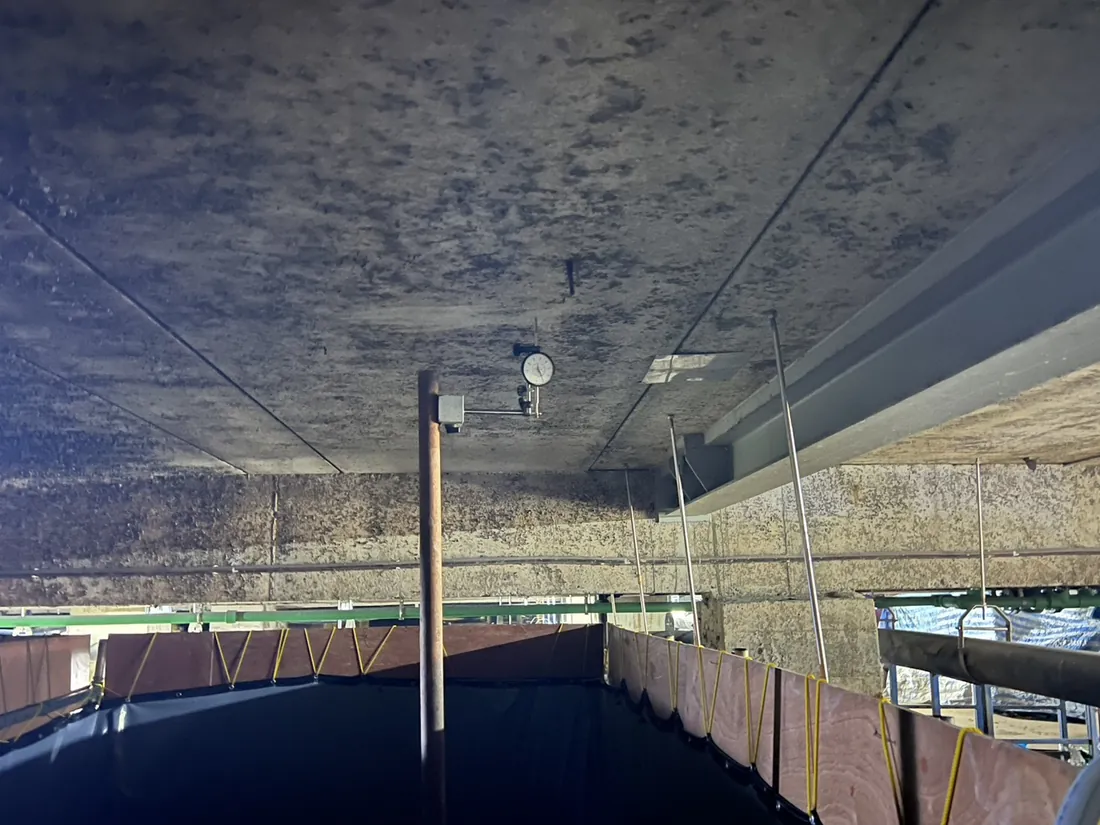
Details of staged loading, calculating the total test load and the ACI acceptance criteria are covered in full on Floor Load Test: Testing Floors with Real Loads. For choosing a loading method on site — water ponding, IBC tanks or sandbags — see Which Loading Method for a Floor Load Test?
What Signs Show a Floor Is Overloaded?
If you see any of the following signs, reduce the load in use first and have an engineer inspect. Do not wait for the damage to spread.
← Scroll to see the full table →
| What you see | Possible meaning | Urgent inspection? |
|---|---|---|
| Parallel cracks on the slab soffit at midspan | Slab bending moment exceeds capacity | Inspect immediately |
| Diagonal cracks around column heads or rack legs | Sign of punching shear | Inspect immediately |
| Slab deflection visible to the naked eye | Slab strength or stiffness insufficient for the load in use | Inspect immediately |
| Localized differential settlement where heavy goods are stored | Subgrade settlement, or slab on ground overloaded | Inspect immediately |
| Concrete spalling exposing rusted rebar | Concrete deterioration; reduced load-carrying cross-section | Inspect immediately |
| Fine map cracking on the surface, not widening | Usually concrete shrinkage cracking | Can be monitored |
Cracks tell you something is wrong, but not how much strength the floor has left. Whether it can stay in use, and up to what load level, must be assessed and signed off only by the responsible engineer.
Changing How a Space Is Used: What Must You Do First?
First state the new working loads as numbers, then have an engineer compare them with the existing floor data. The most common case is leasing an old warehouse that used to store light goods and converting it to high-bay racking or installing machinery. The recommended sequence has 5 steps:
- State the new working loads as numbers — weight per pallet, number of rack levels, leg spacing, and the weight of machinery and forklifts to be used
- Request existing documents from the building owner — as-built drawings, calculations, concrete and pile test results, and the history of extensions
- Have an engineer inspect the site and compare it with the new working loads — if the documents are complete and the margin is large, further testing may not be needed
- Test only the points still unanswered — a Floor Load Test at critical points, or Parallel Seismic when the existing pile length is unknown
- Summarize usage limits that can be written into a contract — e.g. maximum load per square meter, per rack leg, and a zone plan showing where heavy goods may be placed
If you are about to buy or lease a whole building, floor load capacity is only one of 6 categories to inspect. See the full picture in Structural Due Diligence Before Buying or Leasing a Building or Warehouse: What to Inspect
How Much Does It Cost?
Fees for floor inspection and testing depend on the number of points, building area, the load level to be proven and site access, so they are estimated per project. The table below compares relative price levels between items for preliminary budgeting only; these are not actual prices.
← Scroll to see the full table →
| Item | Price level | Remarks |
|---|---|---|
| Rebar scanning + GPR for slab thickness | 💰 | Charged by number of points or scan area |
| Rebound Hammer + UPV for concrete quality | 💰 | Usually done together in one visit |
| Core Test: coring and compressive strength testing | 💰💰 | Includes patching the core holes |
| Plate Bearing Test for slabs on ground | 💰💰 | Needs space to set up kentledge |
| Floor Load Test | 💰💰💰 | Price per test point, depending on load level and kentledge method |
💰 = entry level · 💰💰 = mid level · 💰💰💰 = high level, for comparing items against each other only. Prices exclude travel and equipment mobilization, which are charged extra according to site distance. Get a free quotation within 24 hours via the contact page, or see the overall price structure for inspection work at Structural Inspection & NDT Prices 2026
Summary
The 2023 Ministerial Regulation sets the minimum live load for factory and warehouse floors at 500 kilograms per square meter and prohibits reducing it when designing columns and foundations. But that figure is a design criterion, not an answer to how much the floor of the building you are about to use can actually carry.
An answer you can base decisions on must come from three things together: existing documents and construction drawings, non-destructive on-site inspection results, and actual load testing at critical points. The new working loads must also be converted into point loads at rack legs and vehicle wheels, not just compared as an average per square meter. The final result should be a report certified by a licensed civil engineer (COE license), with signature and registration number, and with usage limits that can actually be written into a lease or a warehouse layout plan.