The method is used for inspecting old buildings, assessments before extensions, and strengthening design. Its key advantage is that it works even when a structure sits on top of the pile heads. This article explains the principle, the procedure, and how it differs from the Seismic Integrity Test, with which it is often confused.
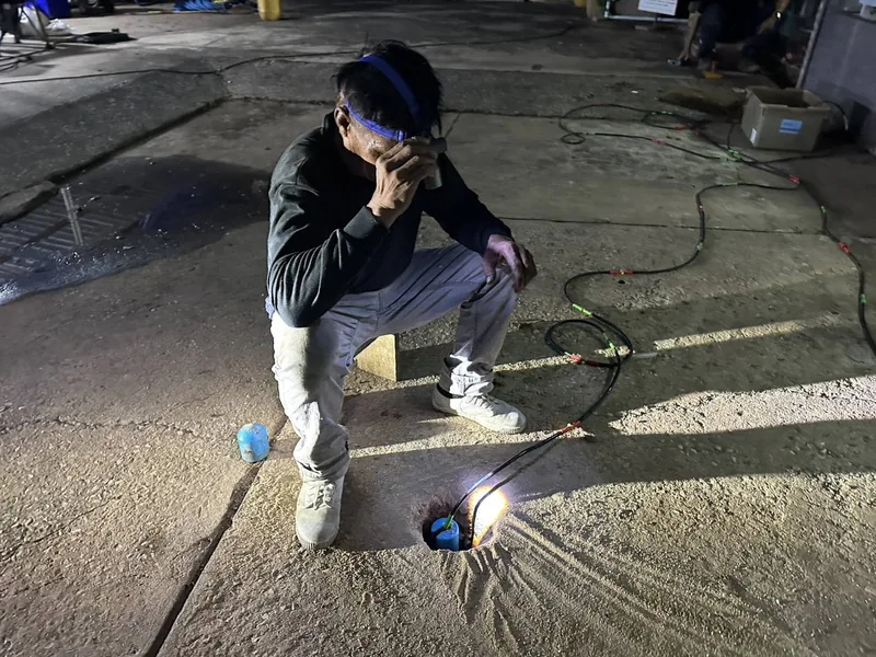
SPN technician lowering a sensor into a borehole beside a footing to measure wave travel time in a Parallel Seismic Test
The SPN team lowers a sensor into a borehole beside a footing to measure wave travel time at each depth — a real Parallel Seismic test on site (photo: SPN Soil Engineering)

How does Parallel Seismic differ from the Seismic Integrity Test?

Both methods use waves generated by a hammer blow, but they answer different questions. The Seismic Integrity Test measures on the pile head to see whether that pile is sound. Parallel Seismic measures in an adjacent borehole to find how deep the existing foundation toe is.

← Scroll to see the full table →

TopicParallel SeismicSeismic Integrity Test (Low Strain)
PurposeFind the depth of existing foundations/piles with no recordsCheck the integrity of new piles (cracks, necking, voids)
SensorLowered into an adjacent borehole Placed on the pile head
Used forExisting structures with a building on topPiles after casting / before construction
What the result showsBreak point of the time–depth plotReflections from the pile toe or defects
Reference standardsASTM D8381DPT 1551-51, using the method of ASTM D5882-16 (withdrawn by ASTM in 2025)
Section comparing the Seismic Integrity Test with the Parallel Seismic Test, and a plot of wave travel time versus depth used to locate the pile toe A two-panel diagram. Panel A is a section of the Seismic Integrity Test, used on new piles whose heads are accessible: the hammer and the sensor are on the pile head, the wave travels down the pile and reflects from the toe back up to the same sensor. It answers whether that pile has cracks, necking or voids, with reference to DPT 1551-51. Panel B is a section of the Parallel Seismic Test, used on existing foundations where a building column and footing sit on the pile heads: the exposed structure is struck, the wave travels down the pile and then through the soil to a sensor lowered into a water-filled casing in an adjacent borehole drilled deeper than the expected pile toe, and the measurement is repeated depth by depth. On the right of panel B is a conceptual plot: the horizontal axis is wave arrival time and the vertical axis is depth on the same levels as the section. Data points alongside the pile line up steeply because the wave travels fast in concrete, while points below the pile toe form a flatter line because the wave must pass through slower soil. The point where the plot changes slope matches the pile toe level, shown by a red dashed line from the pile toe in the section to the break in the plot. This method references ASTM D8381. The bottom strip summarizes three differences: sensor position, what is read from the signal, and the answer obtained. The numbers in the plot are not measured values; it is a conceptual illustration. Seismic Integrity vs Parallel Seismic: different spots, different answers Not to scale A Seismic Integrity Test New pile · head accessible Strike & read at head Hammer + one sensor Wave runs down pile Reflects back up from toe/defect Pile toe Answers: is this pile sound? Cracks, necking, voids · DPT 1551-51 B Parallel Seismic Test Existing footing · structure on pile Footing Column Casing (water) Parallel, close Sensor Read each level Drilled below the expected toe Pile toe level Wave arrival time ← Depth Along pile Steep: fast wave Below toe Flatter: in soil Break Answers: how deep is the existing toe? Read from the time–depth break · ASTM D8381 Conceptual plot, not measured data 1 Sensor position On pile head ↔ in nearby hole 2 What the signal shows Reflection ↔ break in plot 3 Answer obtained Integrity ↔ toe depth
Comparative sections: (A) the Seismic Integrity Test measures at the pile head; (B) the Parallel Seismic Test measures in an adjacent tube, depth by depth, and the break in the plot matches the pile toe level — conceptual illustration, not measured values
💡 Want to know about the Seismic Integrity Test itself?

Read more in the article Seismic Integrity Test for pile integrity, which explains checking new piles directly from the pile head.

How does the Parallel Seismic Test work?

Parallel Seismic relies on the fact that stress waves travel faster in the concrete or steel of a foundation than in the surrounding soil, so a sensor below the pile toe receives the wave noticeably later. The typical procedure has 5 steps.

  1. Drill a borehole beside the foundation, as parallel and as close as possible, deeper than the expected toe level, then install a casing (usually water-filled).
  2. Lower the sensor (hydrophone/geophone) into the casing and move it to measure level by level.
  3. Strike the foundation head or the exposed structure so the wave travels down the foundation.
  4. Record the wave arrival time at the sensor at each depth.
  5. Plot travel time versus depth; the point where the plot changes slope is the foundation toe level.
3D model of a Parallel Seismic test inside an existing building, showing a cased borehole beside the footing, the sensor in the casing, the strike on the building column, and the existing pile in the soil section (conceptual illustration) A conceptual 3D view of a corner inside an existing building. The concrete floor rests on a block of soil cut away to show the fill, soft clay and stiff soil layers below. The section shows a building column on a footing, and below the footing an existing pile of unknown length. Next to the footing is a borehole with a water-filled casing, parallel and close to the pile, drilled deeper than the expected pile toe. A sensor hangs at one level inside the casing, with a cable up to a signal recorder on the floor. One engineer strikes the building column above the footing with a hammer while another reads the recorder. Orange arrows show the wave running down the pile and spreading through the soil to the casing at each level. A red dashed line marks the pile toe level, where the wave travel time changes trend. Numbers 1 to 5 in the view match the steps in the right-hand panel: drill a hole beside the footing and install casing, lower the sensor level by level, strike the exposed structure, record the wave arrival time, and find the break in the plot, which is the foundation toe level. The bottom panel warns that the method gives the foundation toe depth, not the load capacity, and that accuracy depends on the borehole's distance and parallelism. Soil layers and proportions in the view are assumed. 3D model: Parallel Seismic in an existing building, 5 steps Not to scale 1 2 3 4 5 Works even with a building on the piles Red dashed = pile toe level Orange arrows = wave via soil to tube Soil (assumed): Fill Soft clay Firm layer Conceptual; proportions and soil are not real project data 5 test steps 1 Drill beside footing Parallel, close Casing, water-filled 2 Lower sensor in tube Hydrophone / Geophone Read level by level 3 Strike exposed part Footing head/column Wave runs down 4 Record arrival time At every depth Full tube length 5 Find the plot break Travel time vs depth = foundation toe Key limitations Gives foundation toe depth Not the load capacity Accuracy depends on hole spacing & parallelism
Conceptual 3D model of a Parallel Seismic test inside an existing building; numbers 1–5 match the test steps. Proportions and soil layers are assumed.
Principle diagram of the Parallel Seismic Test showing the strike on the structure, a water-filled cased borehole beside the foundation, a hydrophone sensor and a signal recorder
Principle of the Parallel Seismic Test — the superstructure is struck (impactor) so the wave travels down the foundation, and the arrival time is measured at a hydrophone lowered into a water-filled cased borehole nearby. The borehole should be as close to the foundation as possible and drilled deeper than the expected toe level.

When is Parallel Seismic used?

It is used when the depth of an existing foundation must be known but there are no supporting records or the pile heads cannot be reached. There are 4 common cases.

Because an adjacent borehole is needed, the borehole locations must first be planned against actual site conditions. The results are usually overlaid on the soil layers from a soil investigation so the engineer can assess the existing foundation. See real results in Case Study: Parallel Seismic + soil boring at a factory in Samut Prakan.

SPN team using a tripod rig to drill an investigation hole beside a footing inside an existing building to install casing for a Parallel Seismic Test
The SPN team drills an investigation hole beside a footing inside an existing building to install casing for the sensor — Parallel Seismic work is possible even with structure on the pile heads and limited working space (photo: SPN Soil Engineering)

What are the limitations of Parallel Seismic?

There are 3 main limitations.

  • Borehole location — if the hole is too far from or inclined away from the foundation, the results will be in error.
  • Interpretation — picking the break point of the plot requires an experienced specialist.
  • Scope of the answer — the method mainly gives the "toe depth"; it does not give load capacity, which must be assessed by other methods and by the responsible engineer.

SPN Soil Engineering inspects existing foundations and provides full-service NDT. Reports are certified by a civil engineer licensed by the Council of Engineers Thailand (COE), with signature and registration number. Contact us for a free quotation within 24 hours.