What Is the Plate Bearing Test?
The Plate Bearing Test, or Plate Load Test, is a field test in which a rigid steel plate transfers load onto the soil at foundation level in increments, while the relationship between applied pressure and plate settlement is recorded. The results answer two engineering questions directly: the bearing capacity of the soil, i.e. how much load it can carry before failure, and the modulus of subgrade reaction (k), a key parameter in the design of spread footings and concrete pavement structures.
What sets the Plate Bearing Test apart from soil investigation is that boring gives a "profile of soil layers with depth" for overall design, while the Plate Bearing Test measures the soil's "actual load-bearing behavior" at the exact location and level where the foundation will sit. It is therefore a concrete, in-field check of design assumptions, which is why engineers use the two methods together rather than one in place of the other.

What Soil Mechanics Principles Underlie the Plate Bearing Test?
The Plate Bearing Test models a small foundation with a steel plate. As the plate is loaded, stress spreads into the soil as a "stress bulb" whose influence extends to roughly 1.5–2 times the plate width (B), so the measured behavior reflects only the shallow zone beneath the plate. When applied pressure is plotted against settlement (the load–settlement curve), the shape of the curve immediately indicates the soil's failure mode:
- General shear failure — occurs in stiff soil/dense sand; the curve breaks sharply at failure, so the ultimate bearing capacity can be read directly
- Local/punching shear failure — occurs in soft soil/loose sand; the curve bends continuously with no clear break, so a settlement criterion or the tangent intersection method is needed for interpretation
Another principle at the heart of interpretation is that cohesive soils (clay) and cohesionless soils (sand) respond differently to foundation size. In clay, bearing capacity does not depend on footing size, but settlement increases with size; in sand, bearing capacity increases with footing size. This difference is why results from a small test plate must be "scaled" to the real foundation using different sets of formulas (see the calculation section below).
Which Standards Apply to the Plate Bearing Test?
The main standard for the Plate Bearing Test in Thailand is DPT 1253-62, while the active international standards are ASTM D1195/D1195M (repetitive loading) and ASTM D1196/D1196M (nonrepetitive loading). The choice depends on the purpose of the work, as shown in the table:
← Scroll to see the full table →
| Standard | Scope of use |
|---|---|
| DPT 1253-62 | Thai Department of Public Works and Town & Country Planning (DPT) standard — Test for bearing capacity of ground (Plate Bearing Test); the Thai standard referenced directly for work in Thailand |
| ASTM D1196 / D1196M | Nonrepetitive Static Plate Load Test — determines the load–settlement relationship for evaluating and designing highway and airport pavements |
| ASTM D1195 / D1195M | Repetitive Static Plate Load Test — repeated-load test used to determine the elastic modulus of pavement layers |
| ASTM D1194 (withdrawn) | Formerly the standard for soil bearing capacity for spread footings; now withdrawn, but many Thai project specifications still cite it |
| BS 1377-9 | UK standard for field testing, including the in-situ plate loading test |
| IS 1888 | Indian standard, Method of Load Test on Soils, widely referenced in the region |
| AASHTO / Department of Highways | Used to determine the modulus of subgrade reaction (k) for rigid (concrete) pavement design |
Note: when citing standards, check the latest edition from ASTM, and Thai requirements from the Department of Public Works and Town & Country Planning (DPT) and the Engineering Institute of Thailand (EIT)
As for which projects are "required by law" to carry out a Plate Bearing Test, see the conditions under the 2023 Ministerial Regulation on foundations in the article When Is a Plate Bearing Test Required by Law?
What Equipment Is Used, and How Is It Calibrated?
A Plate Bearing Test setup has four main parts: the test plate, the loading system, the reaction system and the settlement gauges. Each one directly affects the accuracy of the results:

- Bearing plate — a rigid circular/square plate at least 25 mm thick, in standard sizes of 300, 450, 600 and 750 mm (often stacked so the plate stays stiff and distributes load evenly)
- Hydraulic jack + pressure gauge/load cell — applies the load and measures the applied force, calibrated
- Reaction system — kentledge or anchors/reaction piles, providing the reaction the jack pushes against
- Settlement gauges (dial gauge / LVDT) — 2–4 gauges around the plate, mounted on a reference beam outside the zone of influence; readings are averaged to reduce errors from tilting
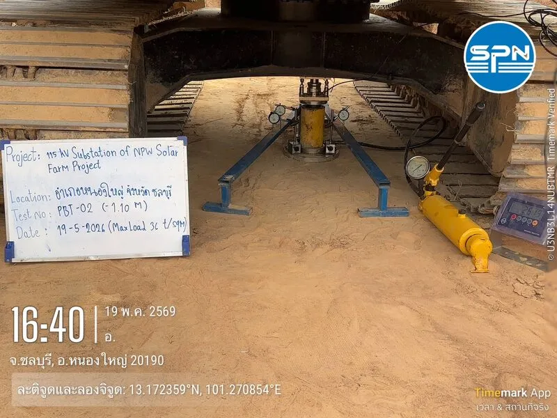
Besides kentledge, sites with limited space often use a backhoe as the reaction load: the machine straddles the test point and the hydraulic jack is placed under the undercarriage between the tracks. The figures below show the full equipment layout as a 2D model (cross-section) and a 3D model, making the positions of the reference beams, settlement gauges and load path clear.
The jack, pressure gauge and load cell must be calibrated by an accredited laboratory, and the reference beam for the settlement gauges must rest on pins placed far enough from the plate and the reaction supports; otherwise the settlement readings will be in error.

How Is the Test Performed and the Data Recorded?
The Plate Bearing Test procedure has six main steps, from preparing the pit to unloading. Each step has clear time criteria and data to record, as shown in the table:
← Scroll to see the full table →
| Step | What to do | Time/criterion | Data recorded |
|---|---|---|---|
| 1. Prepare test pit | Excavate to the design foundation level, level the soil surface, and seat the plate on a thin layer of leveling sand for full contact | Before testing — avoid disturbing the pit bottom | Pit level, condition of soil at pit bottom, plate size used |
| 2. Install equipment | Install the hydraulic jack, reaction system (kentledge/anchors) and 2–4 settlement gauges on the reference beam, then zero them | Force-measuring devices must be calibrated | Initial (zero) readings of all gauges |
| 3. Apply first increment | Increase load in increments of about 1/5 of the expected ultimate load (or equal to the design pressure) | Load slowly and steadily | Applied pressure from gauge/load cell |
| 4. Hold load and record | Hold each increment until settlement stabilizes, then apply the next | Settlement rate below 0.02–0.025 mm/min, or the time specified by the standard | Settlement from all gauges at the specified time intervals in each increment |
| 5. Test to termination criterion | Repeat steps 3–4 until failure occurs or the specified criterion is reached | Settlement reaches the limit (e.g. 25 mm) or load reaches 1.5–3 times the design load | Load–settlement at termination, failure mode (if any) |
| 6. Unload | Reduce the load in steps to zero, then plot the load–settlement curve | Wait until rebound readings stabilize | Rebound and permanent settlement |
Complete load–settlement data from every increment is the key input for analysis. If records are incomplete or the reference beam is disturbed during the test, the whole curve will be misinterpreted.
How Are the Results Analyzed and Calculated?
Analyzing a Plate Bearing Test means reading the load–settlement curve to obtain the bearing capacity and k value, then "scaling" the values from the small test plate to the larger real foundation using soil mechanics formulas. It starts with reading the shape of the curve, as shown in the figure.
1. Ultimate Bearing Capacity
The relationship between plate bearing capacity and that of the real foundation depends on soil type:
2. Predicting Settlement of the Real Foundation
Under the same applied pressure, settlement of the real footing is estimated from plate settlement using the Terzaghi & Peck (1948) formulas:
3. Modulus of Subgrade Reaction (k)
The k value is the slope of the pressure–settlement curve, widely used in concrete pavement design and in beam/raft-on-elastic-foundation analysis:
The k value from the test plate must still be corrected for the size of the real footing/slab before use in design (Terzaghi, 1955):
Applying bearing capacity or k from a small plate directly to a real foundation without size correction is a common and dangerous mistake, especially in sand, where both strength and settlement are highly sensitive to size.
What Types of Projects Use the Plate Bearing Test?
Applications of the Plate Bearing Test fall into two main groups — building foundations and roads/concrete slabs — each needing a different answer from the test:
Foundations and Buildings
- Confirm soil bearing capacity for spread/raft footings of low-rise buildings and lightly loaded structures
- Acceptance testing of compacted fill or ground improvement to confirm it carries the design load
- Design of factory floors/slabs on grade for live loads

Roads and Concrete Slabs
- Determine k (modulus of subgrade reaction) for rigid (concrete) pavement design based on Westergaard theory
- Acceptance of subgrade/subbase layers, concrete yards, parking areas and airport runways/taxiways
What Are the Limitations of the Plate Bearing Test?
The main limitation of the Plate Bearing Test is that the test plate's zone of influence covers only the shallow soil beneath it, so the results cannot fully replace a soil investigation:
The test plate influences soil only to about 2 times its width. If a soft layer lies deeper than that beneath a much larger real foundation, the results will "look better than reality" and lead to an unsafe design, so the test must always be combined with a soil investigation.
- Scale effect — very pronounced in sand; formulas must be applied before using results for the real foundation
- Does not reflect long-term settlement in clay — the test is short, so it does not capture consolidation settlement, which takes months to years
- Requires a large reaction load — high-capacity tests need large amounts of kentledge/anchors, which are limited by site space and safety
- Sensitive to pit-bottom disturbance — disturbed soil at the pit bottom and poor leveling cause errors in results

What Must Be Prepared Before Testing, and When Is the Test Required by Law?
Results are only valid if the site is ready before the test team arrives. The contractor must excavate to the design foundation bottom level, open the pit to at least 4 times the plate size, provide a reaction load at least 1.2 times the maximum test load, and dig drainage trenches to keep water out of the pit bottom — see the site layout and full checklist at How to Prepare the Site for a Plate Bearing Test
On the legal side, the Ministerial Regulation on building foundations B.E. 2566 (2023) requires that spread footings designed for an allowable bearing pressure above 200 kPa (approx. 20 t/m²) be verified by a Plate Bearing Test on the actual site, based on a factor of safety FS = 3 — read who is responsible and when to plan for it at When Is a Plate Bearing Test Required by Law? The 200 kPa Threshold
How Does the Plate Bearing Test Differ from Other Soil Tests?
The key difference is that the Plate Bearing Test measures "actual load bearing" at shallow foundation level, while other methods provide soil profile data with depth. Engineers therefore often combine several methods to get a complete picture:
- Plate Bearing Test — tests "actual" load bearing at shallow foundation level, giving bearing capacity and k directly
- SPT (N-Value) — measures soil density/stiffness with depth; suited to deep pile design
- CPT (Cone Penetration Test) — measures resistance continuously; suited to detailed stratification of soft soils
- Soil boring — gives the complete soil profile and boring log for overall design
In short, the Plate Bearing Test suits shallow foundations and road works, while piled foundations and high-rise buildings rely mainly on soil investigation. See guidance on choosing a method and price ranges for soil testing. Plate Bearing Test fees depend on the number of points, plate size and the reaction system required — contact us for a free quote within 24 hrs at 064-746-9601 or LINE @spnth
This article is provided as engineering knowledge. The choice of plate size, loading criteria and interpretation of results for design should be at the discretion of a licensed engineer and in accordance with the relevant standards.