NDT is used for on-site acceptance of concrete quality, assessing existing buildings before extensions or a change of use, and inspecting damage after fire or earthquakes. This article gives an overview of what each method measures, which questions it answers and when to use it.

What Is NDT for Concrete?

NDT is a set of test methods that assess concrete properties — such as compressive strength, uniformity, rebar location, voids, cracks and corrosion — without damaging the structure, unlike destructive tests that require cutting or drilling out specimens.

The advantages are speed, the ability to retest the same spot, wide coverage and no disruption to the building's use. The limitation is that most methods give "comparative or estimated" values, so they must be calibrated against actual test results, such as Core Tests, before being interpreted as reliable numbers.

How Many NDT Methods Are There for Concrete? Grouped by What You Need to Know

For buildings and concrete structures in Thailand there are 6 main methods in 4 groups, used together with one more method, the Core Test. Many of the methods have a Thai standard alongside the international one: the DPT 1501-51 to 1507-51 series of the Department of Public Works and Town & Country Planning.

← Scroll to see the full table →

Test methodMeasuresReference standardsDestructive
Rebound Hammer (Schmidt hammer)Surface hardness → estimated compressive strengthASTM C805 · DPT 1502-51No
Ultrasonic Pulse Velocity (UPV)Uniformity, voids, cracksASTM C597 · DPT 1504-51No
Ground Penetrating Radar (GPR)Rebar, voids, embedded pipesASTM D6432 / ACI 228.2R · DPT 1507-51No
Cover Meter / Rebar ScannerRebar location + coverBS 1881-204 · DPT 1505-51No
Half-Cell PotentialRebar corrosion riskASTM C876 · DPT 1506-51No
Impact EchoVoids / slab thicknessASTM C1383No
Concrete Core TestActual compressive strength of concreteASTM C42 · DPT 1501-51Semi-destructive
2D section mapping 7 NDT methods for concrete on a single reinforced concrete member, showing what each method can see inside the concrete A conceptual illustration. At the top is a section through a reinforced concrete slab with top and bottom reinforcement, an internal void, an embedded pipe, a crack and corroded rebar. Seven instruments are arranged from left to right. Number one, the Rebound Hammer, presses on the surface and reads only the hardness of the surface zone about 30 millimeters deep. Number two, UPV, has a transmitter on top and a receiver below, with ultrasonic waves traveling through the full thickness. Number three, Impact Echo, taps the surface and receives waves reflected from a void or the slab soffit. Number four, GPR, is a push cart emitting electromagnetic waves, showing hyperbolic signals above the reinforcement and embedded pipe. Number five, the Cover Meter, measures rebar location and concrete cover. Number six, Half-Cell Potential, uses a reference electrode touching the surface and a lead connected to the reinforcement, reading the electrical potential in millivolts to assess the risk of corrosion. Number seven, the Core Test, drills out a concrete core for compression testing; it is a semi-destructive method that gives the actual compressive strength and is used to calibrate NDT results. Below are seven cards stating what each method measures and its reference standards: ASTM C805 with DPT 1502-51, ASTM C597 with DPT 1504-51, ASTM C1383, ASTM D6432 with ACI 228.2R, BS 1881-204 with DPT 1505-51, ASTM C876 with DPT 1506-51, and ASTM C42 with C39. The bottom strip explains the colors of the method groups. NDT method map: what 7 methods see in the same concrete member Not to scale mV 1 Rebound 2 UPV 3 Impact Echo 4 GPR 5 Cover Meter 6 Half-Cell 7 Core Test Section through an RC member (conceptual) Void · pipe · crack · corroded rebar 1 Rebound Hammer Surface hardness ~30 mm ASTM C805 · DPT 1502-51 2 UPV Uniformity, voids, cracks ASTM C597 · DPT 1504-51 3 Impact Echo Slab thickness / voids ASTM C1383 4 GPR Rebar, pipes, voids ASTM D6432 · ACI 228.2R 5 Cover Meter Rebar location + cover BS 1881-204 · DPT 1505-51 6 Half-Cell Potential Rebar corrosion risk ASTM C876 · DPT 1506-51 7 Core Test (semi-destr.) True strength, calibrates NDT ASTM C42 / C39 Groups: Surface hardness Stress waves Electromagnetic Corrosion Semi-destr. (confirm)
NDT method map on a single reinforced concrete section: each method sees something different, from surface hardness and internal quality to reinforcement and corrosion risk, with the Core Test as a semi-destructive method used to confirm results (conceptual illustration)

1. Surface Hardness — Rebound Hammer

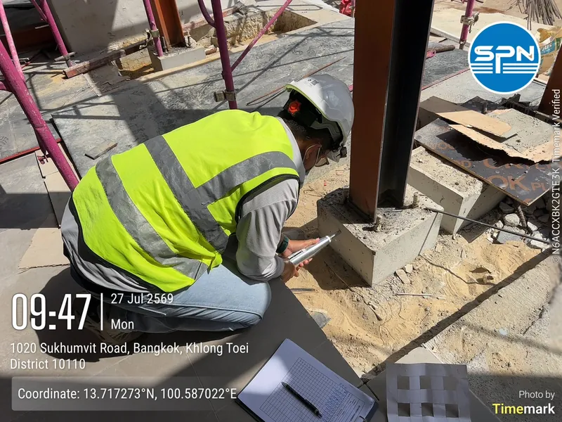
SPN engineer using a Rebound Hammer to test the compressive strength of a concrete pedestal supporting a steel column on a construction site in central Bangkok
A Rebound Hammer measures concrete surface hardness to estimate compressive strength — testing a pedestal supporting a steel column on a real site

The rebound hammer (Schmidt hammer) measures the rebound number from the concrete surface and converts it to an estimated compressive strength using a calibration curve. It is the fastest method, suited to preliminary surveys and comparing uniformity over large areas, but it reflects only the surface zone about 30 mm deep, so it should be used together with other methods. See the on-site procedure in the On-Site Rebound Hammer Test Guide per DPT 1502-51.

2. Stress Waves — UPV and Impact Echo

SPN technicians performing UPV testing on a concrete beam above the ceiling from scaffolding inside a building
UPV measures the velocity of ultrasonic waves through concrete — testing a beam above a suspended ceiling in a real building

UPV (Ultrasonic Pulse Velocity) measures the velocity of ultrasonic waves traveling through concrete. The higher the velocity, the denser and more uniform the concrete; voids or cracks slow the waves or reflect them, so UPV is used to assess internal quality and crack depth. Impact Echo uses stress waves from a mechanical impact to find slab thickness and internal voids.

3. Electromagnetic Methods — GPR and Cover Meter

SPN technician pushing a GPR unit to scan for reinforcement and pipes beneath a concrete slab on a city-center construction site
GPR scanning locates reinforcement, embedded pipes and voids beneath a slab without drilling

GPR (Ground Penetrating Radar) and the Cover Meter locate reinforcement, concrete cover, voids and pipes embedded in concrete, so that drilling or coring can avoid the steel. They are especially useful in renovation of existing buildings.

SPN technicians using a Cover Meter to locate reinforcement on a concrete floor inside a building
Cover Meter / Rebar Scanner locates reinforcement and measures cover — instant results on site without damaging the concrete surface

4. Corrosion Measurement — Half-Cell Potential

Half-Cell Potential measures the electrical potential on the concrete surface to assess the probability that the reinforcement is actively corroding, per ASTM C876. It is suited to older buildings, coastal buildings, or structures showing rust stains and spalling concrete.

5. A Semi-Destructive Method Used with NDT — Core Test

SPN technician drilling concrete core samples from a building floor for compressive strength testing in the laboratory
A Core Test drills out an actual specimen for laboratory testing — giving the most accurate compressive strength and used to calibrate NDT results

The Concrete Core Test drills out actual concrete cores for compressive strength testing in the laboratory per ASTM C42, giving the most accurate compressive strength. It is classed as a "semi-destructive" method and is usually used to confirm results when NDT gives a suspicious signal, or to build calibration curves for the Rebound Hammer and UPV.

Which NDT Method Should You Choose?

The rule for choosing is to start from "the question you need answered", not from the instrument.

  • Need a quick estimate of compressive strength → Rebound Hammer (backed by cores for confirmation)
  • Need to know whether there are internal voids or cracks → UPV or Impact Echo
  • Need to locate rebar before drilling → GPR / Cover Meter
  • Suspect rebar corrosion → Half-Cell Potential
  • Need a verifiable compressive strength figure → Core Test
3D model of a one-storey reinforced concrete building and choosing NDT methods by the question to be answered at 5 test locations (conceptual) A conceptual isometric view of a reinforced concrete building frame with a ground floor slab, six columns, beams and an upper floor slab covering the rear half of the building. There are five numbered test locations. Location one: an engineer uses a Rebound Hammer together with UPV on the front-left column to estimate compressive strength and check concrete uniformity. Location two: an Impact Echo unit sits on the upper slab to find its thickness and internal voids. Location three: a technician pushes a GPR unit along a scan line on the ground floor slab to locate reinforcement and embedded pipes before drilling. Location four: the front-right column has rust stains and spalled concrete and is tested with Half-Cell Potential, with the electrode touching the surface and a voltmeter on the floor. Location five: a core drill stands on the ground floor slab, drilling out a concrete core for compressive testing to confirm and calibrate the NDT results. The box on the right matches questions to methods: estimated compressive strength uses the Rebound Hammer; internal voids or cracks use UPV or Impact Echo; rebar location before drilling uses GPR or Cover Meter; rebar corrosion uses Half-Cell Potential; and a verifiable compressive strength figure uses the Core Test. 3D model: choosing NDT methods by the question you need answered Not to scale 1 · Rebound + UPV 2 · Impact Echo 3 · GPR / Cover Meter 4 · Half-Cell 5 · Core Test 1-storey RC building (front cut away) What to know → which method 1 Approx. compressive strength Rebound Hammer + UPV 2 Internal voids / cracks? UPV or Impact Echo 3 Where is rebar before drilling? GPR / Cover Meter 4 Is the rebar corroding? Half-Cell Potential 5 Verified strength figure Core Test (semi-destr.) Often 2–3 methods together then confirm with cores at key spots Conceptual, not actual layout 1 Start from the question not from the instrument 2 NDT gives relative values Calibrate before interpreting 3 Cores confirm the figures Drill only where necessary
Conceptual 3D view: a single building may use several methods at once, chosen by the question at each location, then confirmed with cores only where necessary

In practice, engineers often combine methods — for example pairing Rebound + UPV (the SonReb method) to estimate concrete strength more accurately — because each method has its own limitations. For weighing the two approaches, read NDT vs Core Test: Which to Choose.

Where Is NDT Used?

GPR scanning to locate reinforcement and pipes beneath a factory floor, with positions marked in paint before coring
Real project example — GPR scanning and marking on a factory floor before coring, to avoid hitting reinforcement and embedded pipes

NDT is most often used in 4 situations: on-site acceptance of concrete quality when cube/cylinder results are questionable; assessing existing buildings before adding floors or changing their use (e.g. a house converted to a café, or a building converted to a warehouse); inspecting damage after fire or earthquakes; and locating rebar or pipes before coring.

NDT reports certified by a civil engineer licensed by the Council of Engineers Thailand (COE), with signature and license number, can be used as supporting documents for safety assessments and permit applications to the relevant authorities, though the outcome remains at that authority's discretion.