In a floor load capacity test, what decides whether the job is practical and how reliable the results are is the way the load is placed on the slab. This article focuses on that alone: the pros and cons of each method, how to arrange the load so the results are not distorted, and how to convert the applied load into kg/m². For the test procedure, total test load calculation and acceptance criteria, see Floor Load Test: Testing Slab Capacity with Real Loads
Why does the loading method matter more than you think?
Because a floor test assumes the applied load is a uniformly distributed load, yet most loading methods apply it in lumps or at points. If the load is poorly arranged, the slab carries forces differently from what the test intends, and the measured values cannot be interpreted against the design.
The problem the standard warns about explicitly is arching action, which occurs when the test-load material is stacked continuously so that it can transfer force across itself — for example, concrete blocks packed tightly into one mass, or sand heaped into a tall mound. As the slab begins to deflect, the stack props itself up into an arch and shifts part of the load to the edges instead of the middle of the slab. The result is that the slab deflects less than it really would, and the reading looks like a "pass" even though the slab never actually carried the full intended load.
ACI 318-19 Chapter 27, which covers strength evaluation of existing structures, requires test loads to be arranged so as not to cause arching action, and to be applied in at least 4 approximately equal increments with measurements at every increment. The chosen loading method must therefore satisfy two things at once: uniform distribution and stepwise loading and unloading.
If the slab shows abnormal behavior during the test, the load must be removed immediately. Methods that are slow to unload, such as heavy materials that must be lifted off pallet by pallet with a forklift, slow the team's decisions at the most critical moment. This is one reason most jobs choose liquid loads.
How many ways are there to load a Floor Load Test?
There are 5 main methods actually used for floor testing in Thailand, each suited to a different situation.
← Scroll to see the full table →
| Loading method | Uniformity | Stepwise control | Unload | Best for |
|---|---|---|---|---|
| Water Ponding | Best, covers full area | Very easy, by water level | Fast, if drainage is available | Ground floors, factory floors with drainage |
| 1,000-liter IBC tank | Good, if laid out in a grid | Good, fill or drain tank by tank | Fast, drain then lift empty tanks | Areas unsuitable for ponding, upper floors |
| 200-liter drum | Moderate, more closely spaced point loads | Good, fine adjustment | Fast | Tight spaces, low headroom, difficult access |
| Sandbags | Moderate, gaps required | Moderate, lifted by hand | Slow, labor-intensive | Small jobs, areas without water supply |
| Materials on site | Depends on material | Medium | Slow, forklift needed | Warehouses already holding goods and forklifts |
The order of consideration is: first check whether ponding is possible; if so, use it, because it is the most uniform and the fastest to complete. Only if ponding is not possible, move down to water-filled tanks, with sandbags or on-site materials as the last resort.
How does water ponding work?
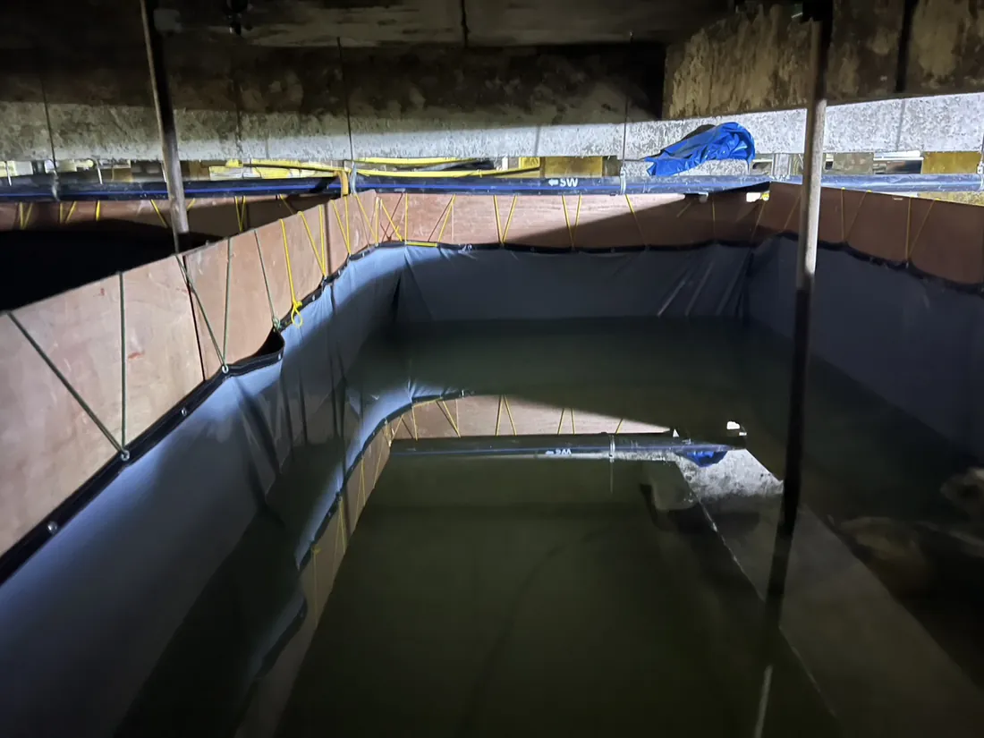
Water ponding means building a temporary watertight pool on the test area and filling it to the depth that gives the required load. Water has a density of about 1,000 kg/m³, so every 10 cm of depth applies exactly 100 kg/m² of distributed load.
An even more important advantage is stepwise control. Simply mark 4 equally spaced water levels on the pool wall and you have the 4 increments the standard requires without lifting anything. To unload, just open a valve or pump the water out, which is far faster than carrying heavy material off.
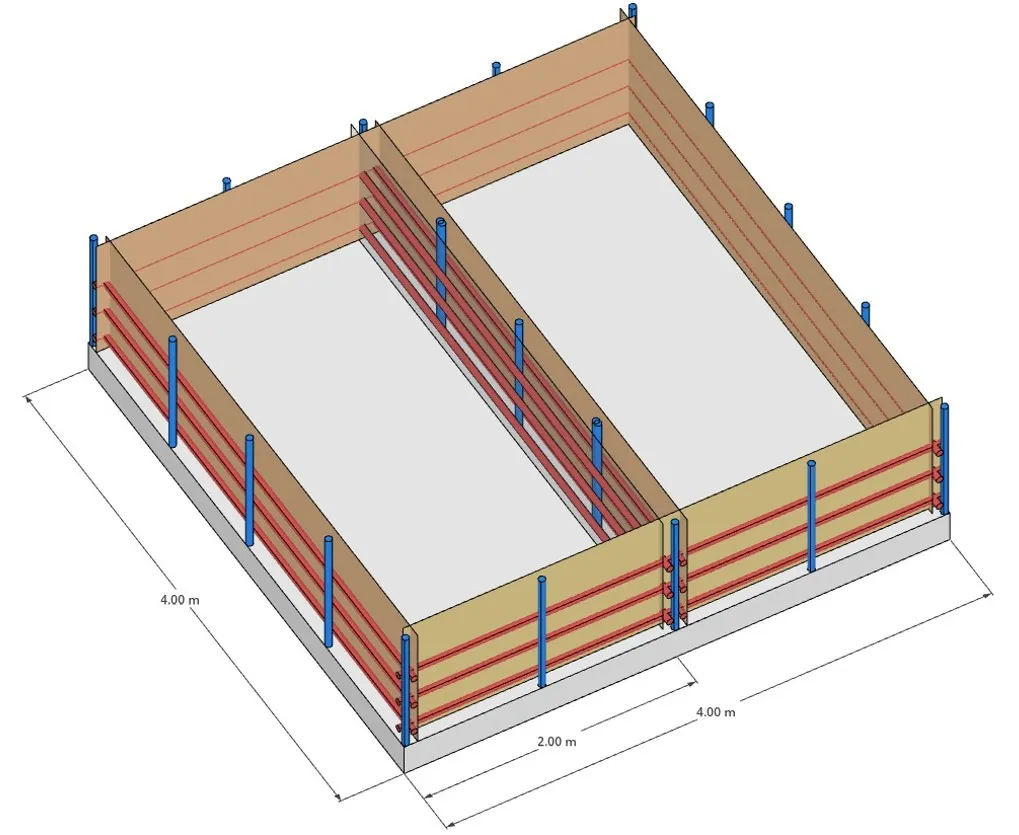
Three things must be in place before choosing this method:
- Pool walls that can resist lateral water pressure — pressure increases linearly with depth, so the total force on the wall increases with the square of the water depth
- A continuous waterproof liner — with no joints where the water is deepest
- A water source and drainage route that can handle the actual volume — a 4×4 m test area at a water depth of 40 cm needs about 6,400 liters; plan both the filling time and the route for releasing the water
How much load does a 1,000-liter IBC tank give, and how should tanks be placed?
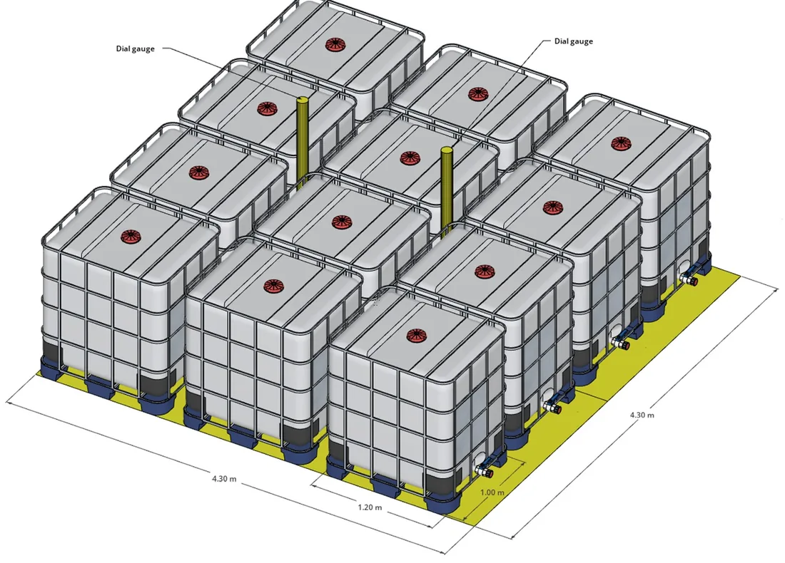
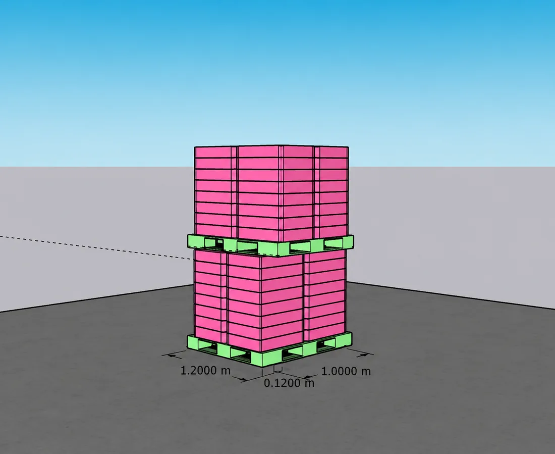
A standard IBC tank filled with 1,000 liters of water weighs about 1,050–1,070 kg in total, including the cage and pallet, on a base of about 1.20 × 1.00 m. Taking only the area under the tank, the bearing pressure is roughly 880 kg/m², far above the design load of a typical slab, so the tanks must be spread out rather than packed together like a raft.
The approach is to define the test area first, then find the number of tanks that brings the average to the target load. As a numerical illustration: a 4.30 × 4.30 m test area is 18.5 m²; place 12 full IBC tanks spread out in a grid.
These figures are only a worked example to explain the approach, not values that apply to every job. The correct test load must be calculated from the design load of that particular slab and the load factors in the standard, as specified by the responsible engineer.
General rules for laying out IBC tanks:
- Keep equal gaps between tanks in every direction — so the bearing pressure is as close to a distributed load as possible, and the tanks do not become a continuous mass that causes arching action
- Never stack tanks two high — besides being dangerous, it doubles the pressure at each point while the average stays the same
- Avoid placing tanks across beams or column heads — the load would go straight into the beam and the slab panel being tested would not receive the full load
- Always fill tanks with water after lifting them into position — lifting full tanks with a forklift creates moving point loads on a slab that has not yet been assessed
- Set load increments by the water level in the tanks, not by the number of tanks — fill all tanks together one quarter at a time, so the load distribution pattern stays the same at every increment, unlike adding tanks one by one, which shifts the load location at every step
Can 200-liter drums, sandbags and on-site materials be used?
All of them can be used, but you must accept their limitations in uniformity and working time. These options are usually chosen when site conditions do not allow the first two methods.
200 L drum
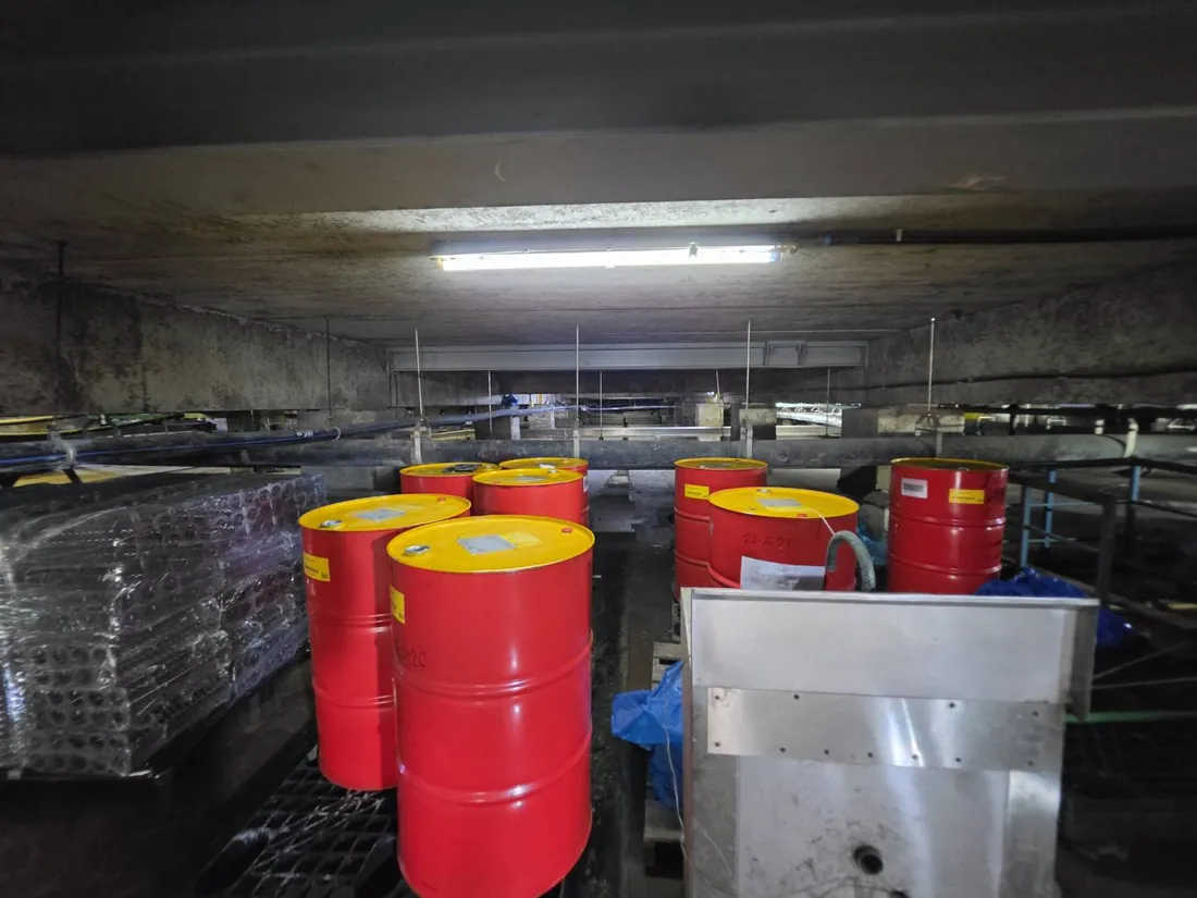
A full 200-liter steel or plastic drum weighs about 210–220 kg on a round base about 58 cm in diameter. The advantages are that drums are easy to move with a drum trolley, fit through narrow doors, and can be used under low ceilings where forklifts cannot enter. The drawbacks are that more units are needed and filling takes longer.
Sandbags
Sandbags hold about 25–30 kg per bag, depending on supply. They are available everywhere and need no water at all. The drawback is that bag weights vary, which is handled by sample-weighing and stating the average value used in the calculation in the report. Another caution is never to heap them into a tall mound, which clearly causes arching action. The usual practice is to place them in small stacks of limited height with gaps between stacks.
On-site materials
Warehouses or factories that already hold bagged cement, rebar or goods together with forklifts sometimes use what is on hand as the test load to save transport costs. The requirement is that the unit weight must be known precisely from weighbridge tickets or labels, not estimated, and the material must be placed on separate pallets with gaps, not as one continuous mass.
The idea that the dead weight must be of known value and placed stably is the same principle as the Kentledge system in static pile load testing. For how to set up the dead-weight system and the precautions involved, see Static Load Test: Choosing Kentledge or Reaction Piles
How should the load be arranged so results are not distorted?
The key principle is that the load must go onto the area analyzed as most critical, and the load itself must not become a structure that helps carry the force. In practice this means the following four points.
- Define the test area boundary before bringing in any load — the location and size of the area must come from analysis of the slab and beam layout, not from whatever open space the forklift can reach most easily
- Leave gaps between load units — the gaps are what prevent arching action; if units sit tight enough to push against each other as the slab deflects, the load is transferred to the edges
- Limit stack height — the taller the stack, the more likely it is to transfer force across itself and the greater the risk of toppling; spreading it low and wide is always better
- Keep the same distribution pattern at every increment — increase the load by adding density at every point at the same time, not by adding material only in certain corners
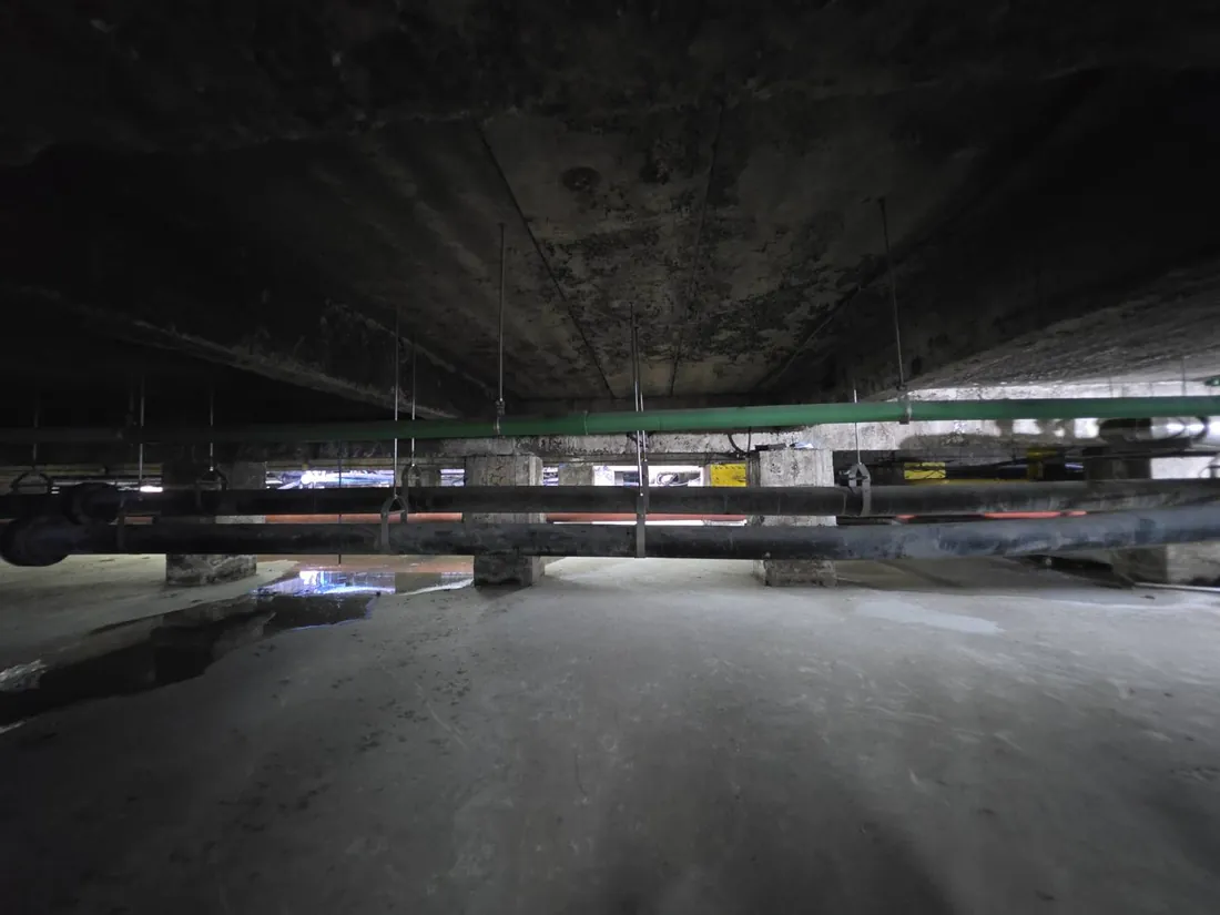
Another point to plan from the outset is where the measuring instruments will be installed under the slab. Many basements have dense MEP services and hangers under the slab soffit, making it hard to find a place to set up Dial Gauge stands independent of the loaded structure. The underside must therefore be surveyed before the test area location is fixed.
How do you convert the applied load into kg/m²?
The formula is the total load actually applied divided by the defined test area. The difficulty is not the division, but defining the denominator correctly and knowing the numerator precisely.
There are three cautions when using this formula:
- Include the weight of the containers — an empty IBC tank with its pallet weighs about 50–70 kg and an empty 200-liter drum about 10–20 kg; counting only the water volume gives a value lower than the actual load
- Do not count open area that was not intended to carry load — the test area must be the boundary defined in advance by analysis, not extended outward until the kg/m² figure looks better
- Verify the actual volume, not the volume printed on the tank — IBC tanks are rarely filled exactly to capacity; use the level marks on the tank side or a water meter at the supply point as recorded evidence in the report
The value from this formula is the average distributed load, which can be compared with the slab's design load, but it does not tell you the local pressure under each tank. Slabs that are thin or have a history of damage therefore need both values considered together. Distributed versus point loads on factory floors is explained in How Much Load Can a Factory Floor Carry?
What if water ponding is not possible?
Switch to water-filled tanks first. Situations that rule out ponding, and the solutions actually used, are as follows.
← Scroll to see the full table →
| Site situation | Reason | Option used |
|---|---|---|
| Upper floor of a building in use | Water leaking to the floor below does more harm than good | IBC tanks or 200-liter drums |
| No drainage near the test area | Water cannot be released after the test | Water-filled tanks; the same water can be reused |
| Low headroom or narrow access | Forklifts and IBC tanks cannot get in | 200-liter drums or sandbags |
| Slab has cracks or joints that cannot be sealed | A pool cannot be built, and water may seep into cracks | Water-filled tanks or on-site materials |
| Area must be returned to the user within one day | Not enough time to fill and drain water | IBC tanks pre-filled off site |
Whatever method is chosen, the same requirements apply: the total load must be known precisely, the distribution must approximate a uniform load, loading and unloading must be possible in increments as the standard requires, and the load must be removable quickly when needed. If the slab to be tested already shows signs of damage, the concrete condition should be checked by non-destructive methods before deciding to load it. See the methods available at this stage in NDT Guide: Non-Destructive Testing of Concrete Structures
Site safety precautions
Site safety depends on preparation before the first load increment. There are 5 things to do on every job:
- Cordon off the area below the test area — no one may be under a slab carrying the test load, except during controlled reading periods
- Have backup shoring ready in advance — prepare temporary shoring under the slab ready to install in case measured values exceed the specified criteria
- Check the stability of the load stacks — especially as the slab begins to deflect, since tanks sitting on a tilting surface can topple
- Plan the drainage route before filling with water — not after the pool is already full
- Watch for cracks throughout the test — record crack locations and widths before starting, to compare with new cracks appearing during the test. For how to record and monitor cracks, see Structural Crack Assessment and Monitoring
What does the cost of a floor load test depend on?
Mainly on the loading method, because it takes the most labor and site time. Cost factors include the size and number of test areas, the target load level, the loading method the site allows, the haul distance for bringing the load into the area, the number of deflection measurement points, and the available working hours.
Contact us for a free quotation within 24 hours. Information that helps us estimate accurately: slab drawings if available, slab thickness, beam spans, the required service load, conditions under the slab, and the access route for bringing materials in. For prices of other structural tests, see Structural Testing Prices 2026
This price excludes travel and equipment mobilization costs, which are charged extra depending on the distance to site.
Summary
The loading method determines whether a floor test reflects the real behavior of the structure. Water ponding is the best method when possible, because it is uniform, controlled in increments by water level, and the fastest to unload.
When ponding is not possible, IBC tanks and 200-liter drums keep the advantage of stepwise control, at the cost of more careful layout work. Sandbags and on-site materials can be used when necessary, but they must be actually weighed, and arching action needs particular attention.
What all methods share is that the load must be known precisely, its location must come from analysis rather than site convenience, and it must be removable immediately when the structure shows signs of distress.
This content summarizes practice for general understanding only. It is not a test specification and not a project-specific work plan. The test load level, test area boundary, load layout and acceptance criteria must be specified and certified by the project's responsible engineer in accordance with the applicable standard.