What Is a Pull-Out Test?
A pull-out test pulls an anchor or stud installed in concrete along its axis while recording both load and displacement, to check whether the fixing system carries its design load. The international reference standard is ASTM E488 — Standard Test Methods for Strength of Anchors in Concrete Elements. It is one type of non-destructive structural evaluation (NDE).
Field testing serves 2 main purposes:
- Proof Load Test — loading to a specified test load (e.g. 1.5–2 times the working load) to confirm the anchor "passes" without failure; used for acceptance of installed work
- Ultimate Load Test — loading until the anchor fails to find its actual ultimate capacity; used to derive design values or compare products
Most on-site acceptance work is proof load testing. Anchors that pass remain in service, because the test load causes no permanent damage. The test records both "load" and "displacement" (load–displacement), rather than only whether the anchor pulls out or not.
The pull-out test in this article tests anchors/studs embedded in concrete to ASTM E488. It is not the same as a pile uplift (tension) load test, which follows ASTM D3689 and pulls an entire pile up out of the ground. If you are looking for pile uplift testing (e.g. for solar farms, transmission towers or underground tanks), see What is a pile uplift (tension) test? instead.
Why Is a Pull-Out Test Needed?
Because the capacity of an anchor as installed can be far below the catalog value. Manufacturer values come from laboratory tests under controlled conditions, but real sites have variables that can reduce capacity:
- Poor hole cleaning — concrete dust left in the hole can reduce the bond of a chemical anchor by as much as 40–60%
- Insufficient embedment — the hole is drilled shallower than specified, or the stud is not inserted to the bottom
- Degraded or incompletely mixed adhesive — stored at the wrong temperature, expired, or the hole not fully filled
- Concrete strength below design, or cracks around the anchor location
- Drilling into reinforcement and relocating without filling the original hole, which can be avoided by scanning for rebar with GPR before drilling
In automated storage and retrieval systems (AS/RS) and high-bay racking, uplift at the column base comes from the overturning moment during an earthquake or a forklift impact. If even one base anchor pulls out, progressive collapse of the whole row can follow. Sample testing before use is therefore a standard requirement of leading racking manufacturers.
Which Types of Anchors Can Be Pull-Out Tested?
Both cast-in and post-installed anchors can be tested. ASTM E488 covers 4 main groups of anchoring systems, which carry load through different mechanisms:
← Scroll to see the full table →
| Type | Characteristics | Load transfer |
|---|---|---|
| Adhesive / Chemical Anchor (bonded anchor) | Threaded stud + epoxy/resin injected into a drilled hole | Chemical bond between the hole wall and the stud |
| Expansion Anchor (wedge/expansion anchor) | Expansion sleeve presses against the hole wall | Friction from expansion |
| Undercut Anchor | Expanded tip in a hole reamed wider at the bottom | Mechanical interlock at the hole bottom |
| Cast-in-Place Anchor (cast in before pouring) | J-bolts, embedded plates cast with the concrete | Bearing of the embedded part |
Chemical anchors must cure for the full time specified by the manufacturer before testing (curing time depends on temperature), and the standard sets a different support clearance for the test rig on chemical anchors than on other anchor types. See the clearance table in the next section.
What Equipment Is Used for a Pull-Out Test?
A field pull-out test rig has 6 main components, which apply load, measure load, measure displacement and transfer the reaction into the concrete:
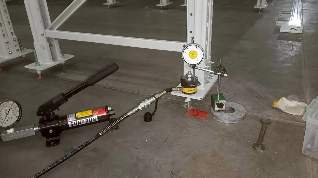
- Hollow ram hydraulic cylinder — fitted over the loading rod connected to the stud
- Hydraulic hand pump with high-pressure hose and coupler
- Calibrated pressure gauge — converts pressure to tension via the calibration equation
- Dial gauge with 0.01 mm resolution on a magnetic stand — measures anchor displacement
- Reaction bridge — transfers the reaction into the concrete at the distance from the anchor required by the standard
- Loading rod and coupling nut — sized to develop the anchor's capacity with minimal elongation
Minimum support clearance under ASTM E488 (tension):
← Scroll to see the full table →
| Anchor type | Support clearance | Clearance to edge/test frame |
|---|---|---|
| Chemical anchor (adhesive) | 2.0 hef | 1.0 hef |
| All other anchor types | 4.0 hef | 2.0 hef |
(hef = effective embedment depth of the anchor)
ASTM E488 requires load measuring equipment for field work to be accurate within ±2% of the applied load. The cylinder + pump + gauge set must be calibrated together against a reference load cell to obtain a conversion equation, e.g. actual load (kg) = gauge reading (bar) × 17.859 − 33.431, and the dial gauge must have a valid calibration certificate.
How Is a Step Loading Test Performed?
Start with a seating load of no more than 5%, then increase the load in steps of no more than 15% of the maximum test load, holding each step for 2 minutes. ASTM E488 allows 2 loading methods: continuous loading or incremental (step) loading. Field work favors step loading because readings can be taken from a manual gauge and the anchor's creep behavior can be seen at each step — the same principle as a static pile load test, where load is applied in steps and displacement is measured.
- Seating load — apply an initial seating load of no more than 5% of the maximum test load so that all components bed in, then zero the dial gauge (this value is the datum)
- Increase the load in steps — each step no more than 15% of the maximum test load
- Hold each step for 2 minutes — read the dial gauge at the start of the hold and at 2 minutes (the 2-minute value is the reported value)
- Record the start and end time of every step and plot the load–displacement curve continuously throughout the test
Example loading sequence (20 kN test load, 15% steps):
← Scroll to see the full table →
| Step | % of max. load | Tension (kN) | Hold (min) |
|---|---|---|---|
| Seating | 5% | 1 | — |
| 1 | 15% | 3 | 2 |
| 2 | 30% | 6 | 2 |
| 3 | 45% | 9 | 2 |
| 4 | 60% | 12 | 2 |
| 5 | 75% | 15 | 2 |
| 6 | 90% | 18 | 2 |
| 7 | 100% | 20 | 2 |
Total hold time is about 14 minutes per point (excluding setup and step changes).
If the dial gauge needle keeps moving while the load is held constant, that is a sign of bond creep. If the displacement does not stop or the gauge pressure drops on its own, the bond is failing; record it as a bond failure even if the anchor has not visibly pulled out.
What Are the Failure Criteria?
ASTM E488 classifies tension anchor failures into 5 modes. Damage may occur in any one mode or several in combination:
- Shear-Cone Failure — the concrete fails as a shear cone around the anchor
- Concrete Cracking + Pull-Out — the concrete cracks around the anchor and the anchor then pulls out
- Pull-Out — the anchor pulls out of the hole
- Bond Failure — the bond between anchor and concrete fails, seen as continued displacement while the load is constant or dropping
- Steel / Hardware Fracture — any component of the anchoring system fractures, including nuts and fittings
The anchor carries the full test load with no failure mode at all, and displacement stays within normal limits (no continued creep while the load is held).
How Many Points Should Be Tested?
ASTM E488 requires a minimum of 5 anchors per size to determine mean capacity (reducible to 3 if failure occurs in the steel). For statistical data, the number depends on the coefficient of variation (CoV):
← Scroll to see the full table →
| CoV of test results (%) | Minimum number of samples |
|---|---|
| Not more than 12 | 5 |
| 12 to 15 | 10 |
| More than 15 | 30 |
In practice, acceptance testing usually specifies a sampling rate, such as 2–5% of all anchors or a minimum of 5–10 points, spread across highly loaded locations and work by different installation crews, depending on each project's specification.
Real Test Example: Racking Column Base Studs in a Warehouse
Case study from SPN testing: M16 × 300 mm threaded studs with 125 mm embedment in a concrete slab with f′c = 400 ksc, anchoring the column bases of an automated storage and retrieval system (AS/RS). 10 points were proof load tested to 20 kN by step loading in 15% increments, each held for 2 minutes.
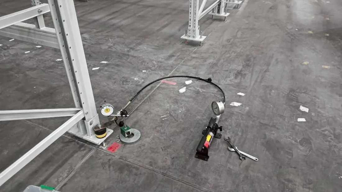
← Scroll to see the full table →
| Item | Result |
|---|---|
| Maximum test load | 20 kN (all points) |
| Failure mode | No failure at any of the 10 points |
| Displacement at maximum load | 0.08 – 0.61 mm (average 0.44 mm) |
| CoV of maximum load | 0.0% |
| Verdict | PASS at all 10 points |
Although every point passed, the displacements differed by a factor of 7 (0.08 vs 0.61 mm). This difference reflects the installation quality at each point, such as hole cleanliness and the integrity of the adhesive. A point with large displacement, even if it passes, gives the site supervisor grounds to go back and review the installation process for that batch. For how to read the load–movement curve and where the displacement values come from in detail, see How to interpret pull-out test results.
Best Practices
Test results are reliable when these 7 points are controlled, from before mobilization through to recording the results:
- Set the test load in writing before mobilization — the proof load comes from the designer or the manufacturer's specification, not from an agreement on site
- Check the calibration certificates every time — the cylinder + pump + gauge set is calibrated together, and the dial gauge has a valid calibration certificate
- Align the load square and concentric — the tension must act exactly along the stud axis; eccentricity causes bending moment and distorted readings
- Mount the dial gauge on a point unaffected by deflection — the magnetic base must be outside the zone of influence of the reaction bridge
- Respect the clearance for each anchor type — 2.0 hef for chemical anchors, 4.0 hef for other anchor types
- Record all data required by the standard — point location, time of each step, gauge reading at 2 minutes and failure mode, with photos of every point
- Never stand in line with the loading rod while loading — if the stud or coupler breaks, parts will fly off along the line of force; always wear safety glasses and use a shield
Summary
A pull-out test to ASTM E488 is the tool for confirming that chemical anchors and threaded studs as actually installed on site carry their design load, not just the catalog value. The keys to a reliable test are calibrated equipment, a correct step loading procedure (5% seating → steps of no more than 15% → 2-minute holds), complete load–displacement records and a number of test points consistent with statistical principles.
SPN Soil Engineering provides pull-out testing of chemical anchors, threaded studs and anchor bolts to ASTM E488, using hydraulic equipment calibrated against a reference load cell and dial gauges with calibration certificates. Results are reported with load–displacement curves and photos of every point, and reports are certified by a civil engineer licensed by the Council of Engineers Thailand (COE), with signature and registration number. We also provide other structural tests, such as the floor load test using real applied loads.
This article is provided as engineering knowledge. The test load, number of points and interpretation of results should follow the project specification and the judgment of a licensed engineer.