What Is a Retaining Wall and When Do You Need One?
A retaining wall is a structure that resists lateral earth pressure so that the ground on either side can sit at different levels without collapsing. It is used wherever soil must be cut or filled to create a level difference, such as hillside houses, parking areas, riverbanks, road embankments and basement excavations. A wall must resist 3 loads at once: earth pressure, water pressure behind the wall, and surcharge load on the backfill. It must therefore be designed from actual soil data and certified by an engineer (see how high a retaining wall can be before an engineer must design it).
When is one needed? In general, a retaining wall is needed in 5 cases:
- A level difference is required but there is not enough space to leave a natural slope
- The ground is filled higher than the adjacent land or road and the fill must be kept from spilling past the boundary
- A basement or deep pit is excavated close to neighboring buildings
- A riverbank or embankment is being eroded by water
- An existing slope shows signs of movement or landslide
If the level difference is small and there is enough space, grading a slope with proper drainage is usually cheaper than building a wall (see slope protection methods).
Summary table for initial selection (approximate values for comparison; for advantages and limitations see the comparison table below):
← Scroll to see the full table →
| Type | Suitable height* | Suitable for | Cost** | Engineer design/certification needed? |
|---|---|---|---|---|
| Gravity Wall | Up to ~2–3 m | Gardens, hillside houses, small level differences | 💰 | Always recommended · required when a building permit is needed, the wall adjoins a boundary or neighboring building, or there is surcharge behind the wall |
| RC L-/T-shaped wall | ~2–8 m | General permanent works: houses, buildings, parking areas | 💰💰 | Required |
| Gabion | ~1–6 m | Roadsides, riverbanks, rural works | 💰💰 | Always recommended · required for multi-tier walls, waterfront sites or walls on a property boundary |
| Sheet Pile | Excavation/riverbank ~2–10 m | Temporary excavation, riverbank protection | 💰💰💰 | Required |
| Bored pile wall | Deep excavation ~6–20 m | Urban basements next to neighbors | 💰💰💰💰 | Required |
| Diaphragm Wall | 15 m+ | Multi-level basements, high-rises, rail transit | 💰💰💰💰💰 | Required |
| MSE Wall | Embankment ~3–20 m | Road embankments, interchanges | 💰💰–💰💰💰 | Required |
*Heights are approximate common ranges; actual values must be set by an engineer from soil data · **Cost levels are relative comparisons between systems, not reference prices · Every retaining wall system must meet the factor-of-safety criteria of the Ministerial Regulation B.E. 2566 (2023), which can only be calculated from actual soil data
What Does a Retaining Wall Design Look Like? (Example Section of an RC L-Shaped Wall)
The most common retaining wall design is the L-shaped reinforced concrete wall (cantilever wall). Its section has 4 main components: the stem, which resists lateral earth pressure; the base slab, divided into the heel, which extends under the backfill so the soil weight helps resist overturning, and the toe at the front; the shear key under the base, which resists sliding; and the drainage system, consisting of a filter layer behind the stem, a perforated drain pipe and weep holes through the wall. Drainage matters as much as the structure, because water trapped behind the wall raises lateral pressure significantly above that of dry soil and is a common cause of retaining wall failure.
How Many Types of Retaining Walls Are There?
Retaining walls used in Thai construction fall into 7 main types. Each resists earth pressure through a different mechanism, so each suits different site conditions. By construction sequence they form 2 groups: walls built up from the base and then backfilled (types 1, 2, 3 and 7), suited to fill works and grade changes; and walls installed into the ground first, with soil then excavated in front (types 4, 5 and 6), suited to excavations, waterfront works and basements.
1. Gravity Wall
A gravity wall uses its own weight to resist earth pressure, e.g. solid cast concrete, stacked concrete blocks or masonry. It suits small level differences (generally no more than 2–3 meters), is easy to build and needs little reinforcement, but the taller it gets, the larger the section must be, so material use climbs quickly with height.
2. L-/T-Shaped Reinforced Concrete Wall (Cantilever Wall)
A cantilever wall, L-shaped or inverted-T, is the most popular type for general permanent works. The weight of soil on its base helps resist overturning, so it uses less concrete than a gravity wall of the same height. The common range is about 2–8 meters. It needs a fair amount of base area behind the wall, and its performance depends directly on the reinforcement design and the soil beneath the base.
3. Gabion
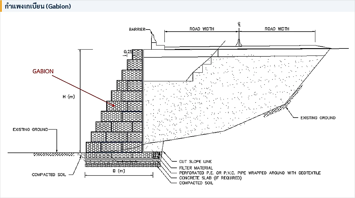
A gabion is a steel wire-mesh basket filled with stone, stacked in steps. Its key advantage is that water drains through it, so no water pressure builds up behind the wall, and it tolerates differential settlement well. It suits roadside slopes, riverbanks, rural works and sites where a natural look is wanted. Its limitations are a large base footprint and the need for corrosion-resistant wire on waterfront works.
4. Sheet Pile
Sheet piles are steel or prestressed concrete sheets driven continuously to form a wall line, locked together by interlock joints. They install fast, need little space and can be extracted and reused (steel), which makes them a popular system for temporary excavations, waterfront works and riverbank protection. Watch for water seepage through the joints, vibration from driving affecting neighboring buildings, and depth limits set by the chosen section.
5. Bored Pile Wall (Contiguous / Secant)
This system uses cast-in-place bored piles placed side by side (contiguous) or overlapping (secant) to form a wall that resists earth pressure. It suits deep urban excavations where vibration is not allowed, such as basements next to neighboring buildings. The secant type also cuts off water better. It is usually combined with bracing/struts or ground anchors depending on the excavation depth. See a real design example in the case study: temporary earth retaining system for a 4-meter deep excavation.
6. Diaphragm Wall
A diaphragm wall is a reinforced concrete wall cast in a trench excavated under supporting slurry. It is the stiffest and most watertight system and gives the best control of ground movement. It is used for very deep excavations such as multi-level basements, high-rise buildings and underground rail stations, at the cost of the highest price and longest preparation time of all the systems.
7. Reinforced Soil (MSE / Reinforced Soil Wall)
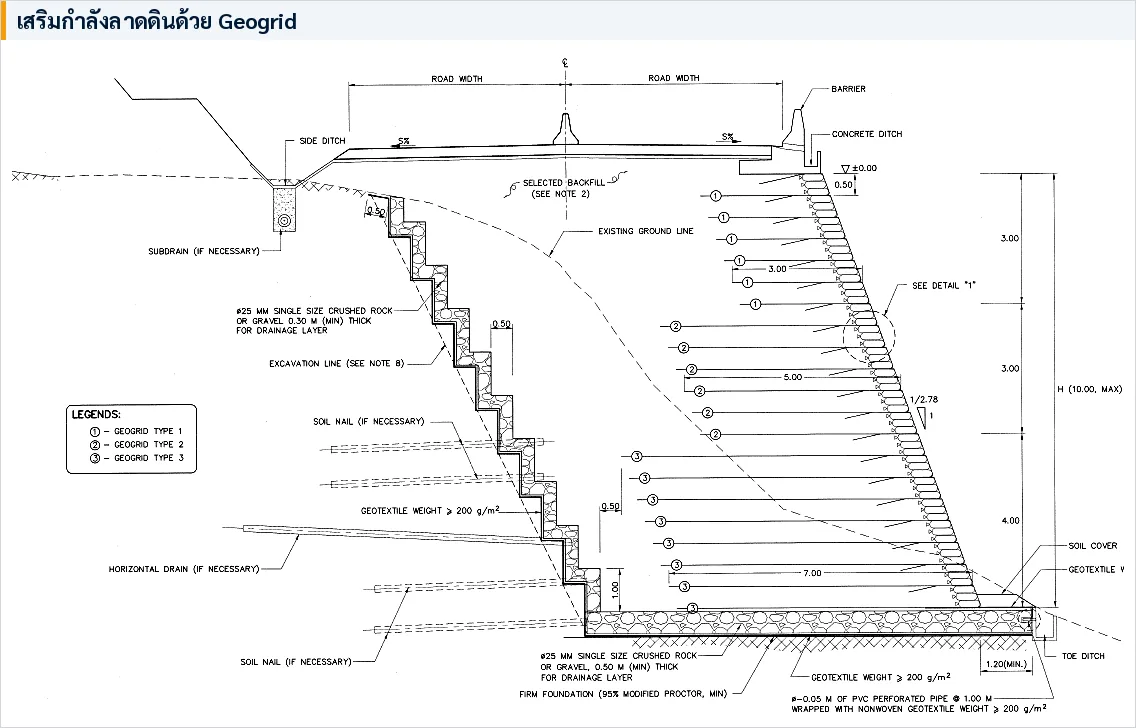
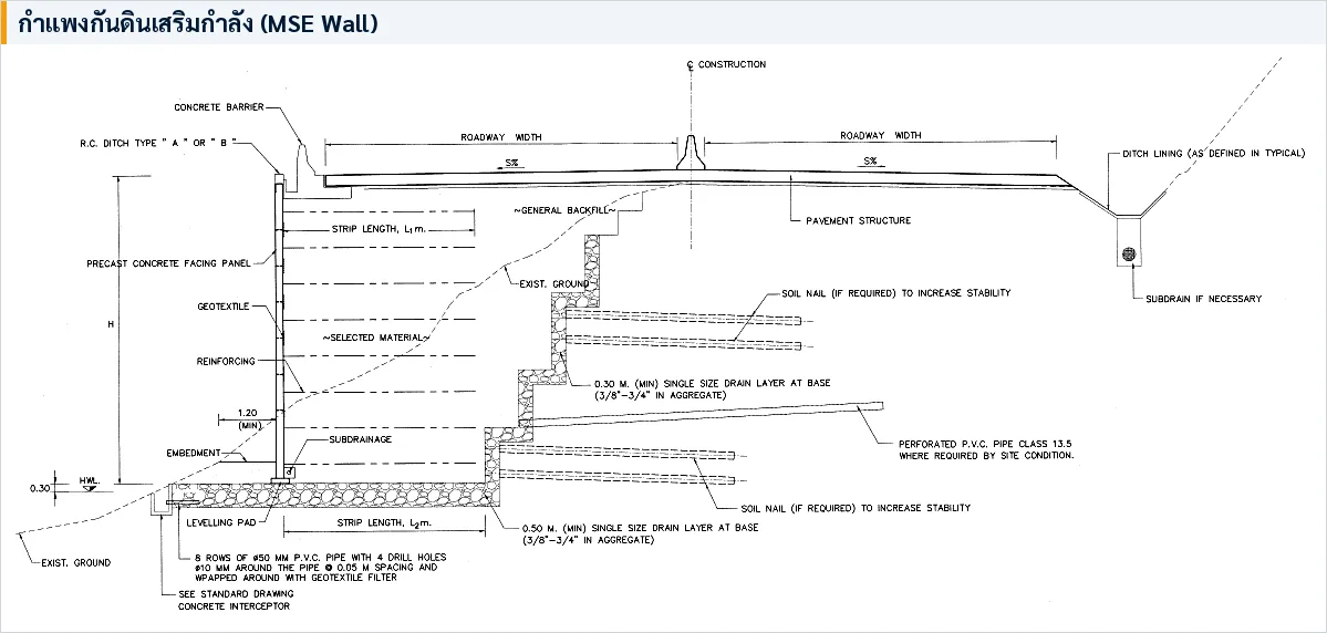
A mechanically stabilized earth (MSE) wall uses geosynthetic sheets (geogrid/geotextile) or steel strips embedded layer by layer in compacted fill, so the soil mass itself acts as the wall. The face is made of precast concrete panels or blocks. It suits road embankments, interchanges and tall walls with enough fill space behind. It is fast to build and economical for the height achievable, but the fill material and compaction must be strictly controlled.
How Do the 7 Retaining Wall Types Differ? (Comparison Table)
This table summarizes the typical range, advantages, limitations and relative cost of all 7 types, for an initial comparison before consulting an engineer.
← Scroll to see the full table →
| Type | Typical range* | Key strength | Limitations | Relative cost** |
|---|---|---|---|---|
| Gravity Wall | Up to ~2–3 m | Simple to build, durable | Material-heavy as height increases | 💰 |
| RC L-shaped wall | ~2–8 m | Cost-effective for general permanent works | Needs base area behind the wall | 💰💰 |
| Gabion | ~1–6 m | Drains well, flexible | Large footprint; wire must resist corrosion | 💰💰 |
| Sheet Pile | Excavation/riverbank ~2–10 m | Fast, tight sites, extractable and reusable | Leakage at interlocks, vibration when driving | 💰💰💰 |
| Bored pile wall | Deep excavation ~6–20 m | Low vibration, suits urban areas | Needs struts/anchors | 💰💰💰💰 |
| Diaphragm Wall | Very deep excavation, 15 m and deeper | Strong, watertight, least deformation | Highest cost and preparation time | 💰💰💰💰💰 |
| MSE Wall | Embankment ~3–20 m | Can be very tall, fast to build | Needs fill space, strict compaction control | 💰💰–💰💰💰 |
*Height/depth ranges are approximate common values for comparison only; actual values for each project must be set by an engineer from actual soil data · **Cost levels are relative comparisons between systems, not reference prices, as they depend on soil conditions, height and each site
How to Choose a Retaining Wall: 5 Factors
The principle of selecting an earth retaining system is to match site conditions to each system's strengths, working through 5 factors:
- Retained height or excavation depth — small level differences allow many options; the taller the wall or deeper the excavation, the more the choice narrows toward bored pile walls or diaphragm walls
- Site space and neighboring buildings — a narrow site close to the boundary rules out systems with a wide base; work next to neighboring buildings must avoid high-vibration systems such as driven sheet piles
- Soil layers and groundwater level — thick soft soil puts shallow walls at risk of both sliding and insufficient bearing; a high groundwater table means water pressure and waterproofing must be considered from the system selection stage. All of this data comes from soil investigation and interpretation of the SPT N-value
- Permanent or temporary — temporary excavations often use extractable sheet piles; permanent works choose concrete or MSE systems with a long service life
- Environment — waterfront works must account for erosion and tidal water levels (see waterfront retaining wall design), which is why gabions and sheet piles are the usual choices for riverbanks, while urban works prioritize control of noise and ground movement
In Central Thailand, on Bangkok soft clay, choosing an earth retaining system calls for extra care, because the soil's shear strength is low and the groundwater is shallow. A system that looks economical on paper may fail the safety criteria when checked against actual soil.
What Are the Slope Protection Methods?
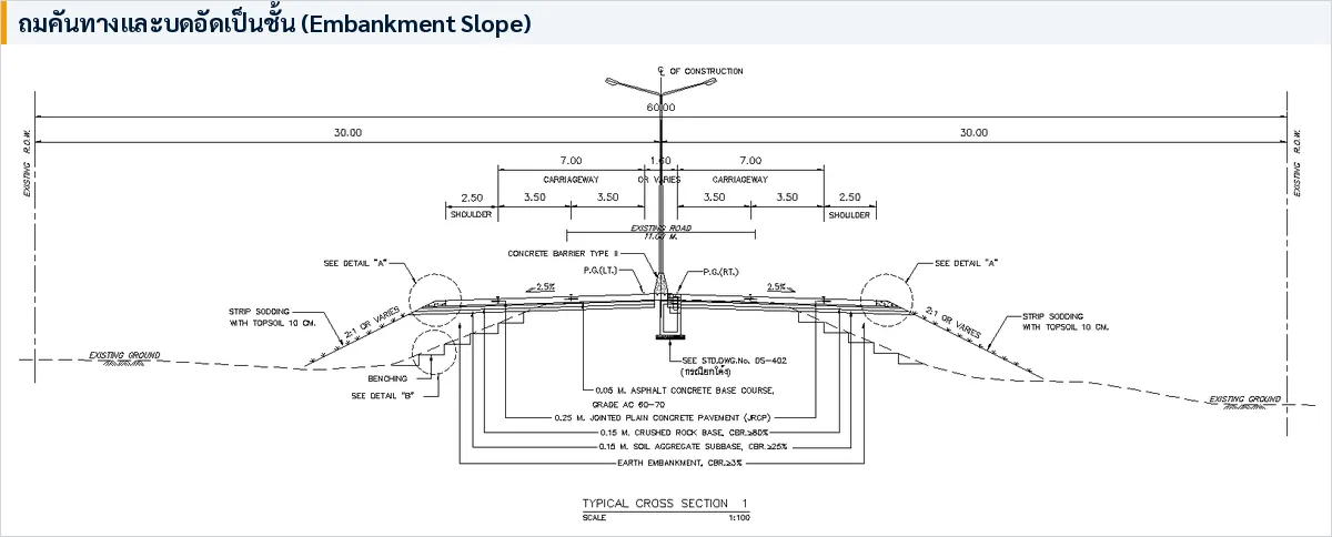
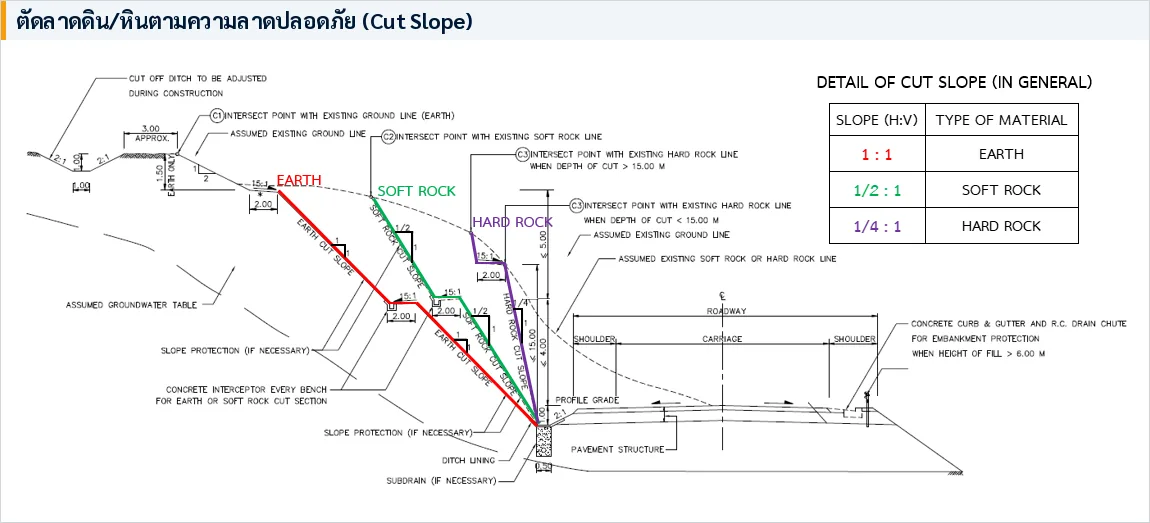
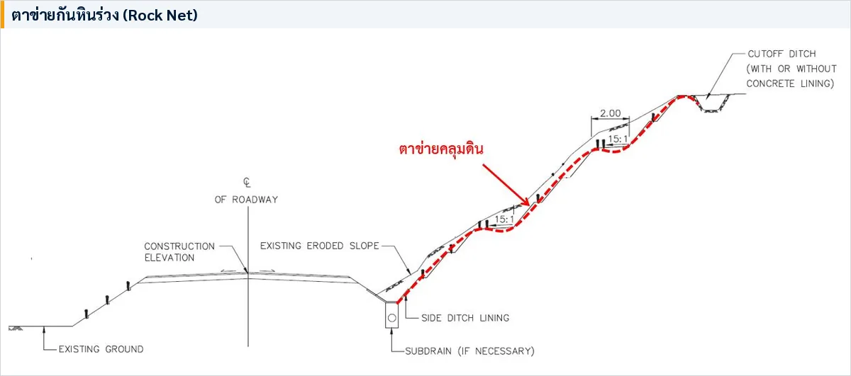
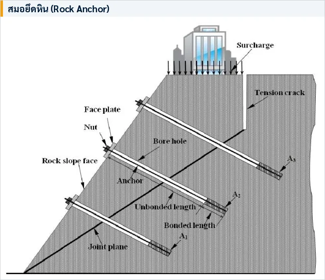
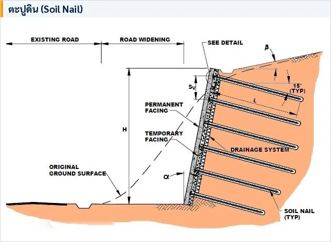
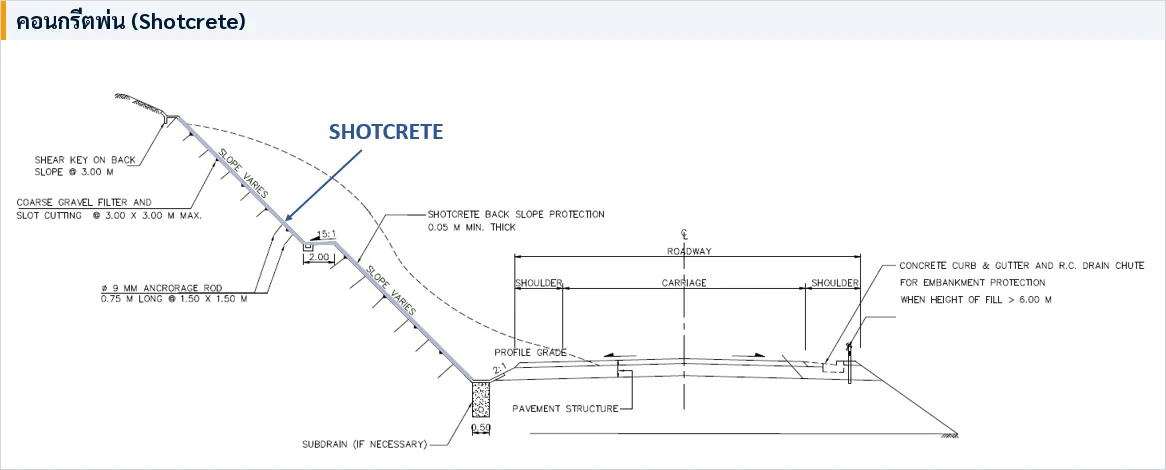
Slope protection is a group of methods that stabilize slopes without building a full retaining wall, widely used in road, embankment and hillside works. There are 8 commonly used methods, ranging from layered compacted fill and cutting soil/rock slopes to safe slope ratios, to reinforcement systems such as geogrid, MSE walls, soil nails, rock anchors, rockfall netting and sprayed concrete (shotcrete). The sections below show what each system looks like and the kind of work it is used for.
What Does the Law Require Before Building a Retaining Wall?
The Ministerial Regulation on Building Foundations and Supporting Ground B.E. 2566 (2023) sets minimum factors of safety for retaining walls in 3 respects, whichever system is chosen:
- Sliding — not less than 1.50
- Overturning — not less than 2.00
- Bearing capacity of the founding soil — not less than 3.00
Criteria used in actual design may be stricter, depending on each project's requirements. Read the full details in Retaining walls under the 2023 Ministerial Regulation: the 3 FS values you must pass
All three values are calculated entirely from actual soil properties, so the correct sequence is soil investigation → engineer selects the system and designs → FS checked against the criteria. SPN provides both soil investigation and testing and geotechnical design, covering every type of retaining structure above.
Summary
Each of the 7 retaining wall types has its place: for small level differences, start with gravity walls, L-shaped walls or gabions; for temporary or waterfront excavations, look at sheet piles; deep urban excavations use bored pile walls or diaphragm walls; and high embankments use MSE. The deciding question is not which type is "best" but which one meets the legal safety criteria at the most reasonable cost on the actual soil of that site — and that answer always starts with a soil investigation.
This article provides general knowledge for preliminary decisions only and is not design advice for any specific project. The selection and design of an actual earth retaining system must be carried out by a licensed engineer using soil investigation data for that site.