Why do piles deviate from their design position?
Deviation of piles from their design position occurs on almost every foundation project and does not always mean the work was faulty. Common causes include:
- Underground obstructions — old concrete debris, tree stumps, boulders or buried old foundations deflect the pile during driving
- Sloping or variable soil layers — the pile tip slides along a sloping hard layer, especially where soil conditions change quickly
- Control of the starting position — the setting-out peg or pile verticality is off from the start
- Soil displacement from driving adjacent piles — especially in closely spaced pile groups in soft clay, where driving later piles can push earlier ones out of position
Because deviation cannot be avoided entirely, the new law is not written as "no deviation allowed". It takes an approach closer to site reality: it requires the design to allow for deviation in advance.
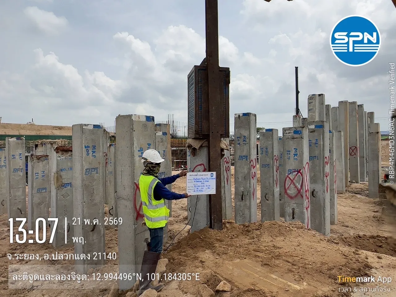
What deviation criteria does the law set? (75 mm / 50 mm / 10%)
The Ministerial Regulation Prescribing Building Foundations and Ground Supporting Buildings B.E. 2566 (2023), in force since 28 February 2024 (see the full overview in our plain-language summary of the 2023 Foundation Ministerial Regulation), sets clear numerical criteria for pile deviation in Clause 28:
← Scroll to see the full table →
| Issue | Criteria under the 2023 Ministerial Regulation (Clause 28) |
|---|---|
| Deviation from center of each pile | The building structure above the foundation must be designed to accommodate at least 75 mm |
| Piles arranged in a single row | Designed to accommodate a deviation of at least 50 mm |
| Effect of deviation on each pile | Must not cause any pile to carry more than its design load by over 10 percent |
The clever part of this requirement is that it does not prohibit pile deviation, but requires the design to allow for deviation in advance. In practice, if the deviation is within what the design allows and the engineer has verified that no pile carries more than 10 percent above its design load, work can proceed. If the deviation is larger, the inspection and remediation process required by the Ministerial Regulation applies.
The mechanism behind the check: when piles in a group deviate unequally, the centroid of the pile group is offset from the center of the column by a distance e. The column load P then produces a moment M = P × e, so some piles carry more load and others less. The 10% criterion is therefore checked on the most heavily loaded pile, not on the group average.
Before this Ministerial Regulation, deviation criteria were usually project-specific (spec) requirements that could be negotiated on site. Now the minimum criteria have been raised to law — so when a pile deviates, the question is no longer "is deviation allowed?" but "how much has it deviated, has it been measured, and has the engineer checked the effects?"
The figure below shows a four-pile foundation layout with unequal deviations, and hypothetical values of the force in each pile for small and large deviation, compared with the +10% limit line.
Found deviated piles on site? 4 steps to take
Step 1 — Survey the actual position of every pile
Measure the coordinates of each pile head against its design position (as-built survey) and document the distance and direction of deviation for each pile. Never judge by eye, because the legal criteria are in millimeters. Every following decision must be based on this measured data.
Step 2 — Send the data to the design engineer for checking
The engineer will analyze the redistribution of load in the pile group, check whether any pile carries more than 10 percent above its design load, and whether the additional moment on the pile cap and column is still within what the structure can carry. This step is the direct responsibility of the project's design engineer.
Step 3 — Check the integrity of piles with large deviation
Piles with large deviation usually raise the question of whether the pile is "broken, cracked or bent" underground. The fastest and most economical screening tool is the Seismic Integrity Test (DPT 1551-51 — ASTM D5882-16 was withdrawn in 2025), which checks the continuity of the pile shaft non-destructively in just a few minutes per pile. If the load capacity of a suspect pile needs to be confirmed, it can be followed by a Dynamic Load Test (PDA) per DPT 1252-51 — see a comparison of pile test methods in Dynamic vs Static Load Test, and if a pile fails the seismic test, see the follow-up checks and remedies in Pile failed the seismic test: what next?
Step 4 — Act on the analysis results
If the analysis shows the criteria are exceeded, the remedy is at the discretion of the design engineer, for example enlarging the pile cap, adding supplementary piles or adjusting the column position — this article gives an overview for understanding only and is not remedial advice for any particular project, because each site has different loads, soil conditions and foundation types.
The 3D model below combines the four steps in a single site view, from surveying actual positions with a total station to checking the integrity of the pile that deviates beyond the allowance.
How can pile deviation be prevented from the start?
- Carry out adequate soil investigation — knowing in advance where hard layers slope or obstructions lie helps plan driving and choose the right pile type (see guidance on the right number and depth of boreholes)
- Control pile driving/boring with periodic position surveys — check coordinates as work progresses rather than measuring once at the end, because problems found early are cheaper to fix
- Test pile integrity with comprehensive seismic testing — especially in zones with hard driving, obstructions or unusual deviation
Is checking deviated piles expensive?
Compared with the risk of continuing construction on problem piles, the cost of testing is very low:
- Seismic Integrity Test — about THB 100–150/pile, suitable for screening large numbers of piles
- Dynamic Load Test (PDA) — from about THB 5,500/pile, used to confirm the load capacity of suspect piles
Both are starting prices; the actual cost depends on the number and size of piles. These prices do not include travel and equipment mobilization costs, which are charged based on the distance to the site.
Summary: a deviated pile is not the end — if it is measured and checked by an engineer
The 2023 Foundation Ministerial Regulation turns pile deviation from an on-site negotiation into clear numerical criteria: the design must allow for 75 mm of deviation (50 mm for piles in a single row), and the effect must not cause any pile to carry more than 10 percent above its design load. When piles deviate, measure them, have the engineer analyze, and check integrity — never judge by eye — and let the design engineer decide whether they pass or need remedial work.
This article summarizes the Ministerial Regulation for general understanding only. It is not legal or engineering advice for any specific project. For practical use, refer to the official text of the Ministerial Regulation as published in the Royal Gazette and consult the licensed engineer for your project.