Failed cylinder or cube results are a common occurrence on construction projects, and the standards lay out a clear sequence of checks, from reviewing the test results and non-destructive testing to drilling cores from the actual structure. This article explains what each step involves, which criteria are used to judge it, and what options remain if the concrete still does not pass.
What compressive strength results count as "failing"?
Concrete is considered to fail when it does not meet either of the two conditions in ACI 318-19 Section 26.12. The criteria do not judge on a single specimen; they look at both the average and the minimum at the same time.
- The average of 3 consecutive test results must be at least the specified compressive strength (f′c) — one "test result" is the average of at least 2 specimens of Ø150 mm or at least 3 specimens of Ø100 mm from the same batch of concrete.
- No test result may fall below f′c by more than 35 kg/cm² (3.5 MPa) — this applies to concrete with f′c not exceeding 350 kg/cm². If f′c is higher, no test result may fall below f′c by more than 0.10 f′c (equivalent to at least 0.90 f′c).
A single result slightly below the design value is therefore not yet a conclusion that the concrete has failed. The first step in solving the problem is to review all the data, not to rush into drilling the structure.
Concrete with f′c = 240 kg/cm² gives 3 consecutive test results of 232, 245 and 251 kg/cm². The average is 242.7, which is not below 240, and the minimum of 232 is still above 240 − 35 = 205, so both conditions are met. These figures are an example to explain the criteria only; decisions on an actual project must be made by the responsible engineer.
First check: what needs to be reviewed?
The first step is to separate "the concrete is genuinely weak" from "the test specimens have a problem", because improper sampling, curing and testing of specimens produces values lower than the true strength. There are 4 items to review.
- Specimen sampling and curing — under ASTM C31, specimens used for acceptance must be cured under standard conditions. If specimens were left in the sun or rain, or not cured for the full period, the results will be abnormally low.
- Compressive strength test method — under ASTM C39, check that the specimen ends are flat and plane, the testing machine is calibrated, and the loading rate is within the specified range.
- Concrete batch documents — delivery tickets, time from mixing to placement, slump, and whether water was added on site, which is the most common cause of low strength.
- Specimen type — cube and cylinder results cannot be used interchangeably. Cylinder strength is generally about 0.8 times cube strength, so results must be compared against the criterion for the specimen type stated in the specification.
If clear deficiencies are found in specimen sampling or curing, those results may not reflect the quality of the concrete in the actual structure, and data must be obtained directly from the structure in the next step.
How does non-destructive testing help?
Non-destructive testing (NDT) is used to screen whether the problem is localized or spread across the whole area, and to select coring locations precisely. It does not replace the actual compressive strength for acceptance decisions.
← Scroll to see the full table →
| Method | Standard | What it tells you | Limitations |
|---|---|---|---|
| Rebound Hammer | ASTM C805 | Surface hardness and uniformity of the concrete; fast and covers many points | Reads only the outer few centimeters; sensitive to moisture and carbonation. It is a surface hardness index, not a direct compressive strength value |
| Ultrasonic Pulse Velocity | ASTM C597 | Uniformity of the concrete, and locations of internal voids and cracks | Pulse velocity is not compressive strength; a project-specific correlation is needed to estimate it |
| Rebar Scanner / GPR | BS 1881-204 (cover meter) / ASTM D6432 (GPR) | Rebar locations and cover; used to choose core locations that avoid reinforcement | Does not give compressive strength; supporting data for planning the coring |
In practice, Rebound Hammer and UPV are usually used first to sweep the area and find zones with abnormally low values, the reinforcement is scanned, and cores are then drilled only in those zones. This means fewer holes to repair and more targeted data. If UPV values come out low, see how to identify the cause in Low UPV Test results: what do they mean?, and read a comparison of the two approaches in NDT vs core test: which to use.
What criteria are used to judge a core test?
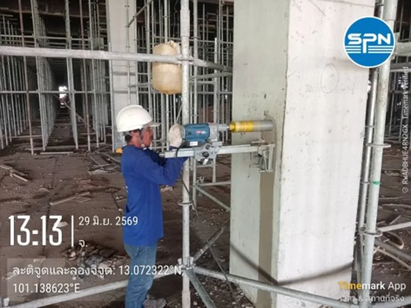
A core test is the drilling of concrete cores from the actual structure for compressive strength testing per ASTM C42. It is the most direct way to answer what the compressive strength of the concrete at that location actually is.
Under ACI 318-19, at least 3 cores are drilled from the area in question and judged on two conditions together: the average of the 3 cores must be at least 0.85 f′c and no single core may be below 0.75 f′c. If both conditions are met, the concrete in the structure is considered acceptable for strength.
Measured values must be corrected for the length-to-diameter ratio (L/D) before comparing with the criteria, because shorter cores give overstated compressive strength.
← Scroll to see the full table →
| L/D ratio | Approximate correction factor |
|---|---|
| 2.00 | 1.00 |
| 1.75 | 0.98 |
| 1.50 | 0.96 |
| 1.25 | 0.93 |
| 1.00 | 0.87 |
Core locations must avoid reinforcement and must not be in critically stressed areas, and they must always be approved by the responsible engineer first. Core holes must be repaired with non-shrink material as specified. The figure below summarizes all three points in one image: selecting core locations, the L/D correction, and an example of judging 3 cores. For details of the test method, read What is a concrete core test?

If the core test still fails, what are the options?
When core tests confirm that compressive strength is below the criteria, the next step is to evaluate whether the structure can still carry its design loads, not to demolish immediately. There are 5 common options, ordered from least to most disruptive.
- Reanalysis using actual strength (re-rating) — use the measured compressive strength to recalculate load capacity. In some cases it is found to be still adequate for the intended use, or adequate once loads are limited.
- Load testing — apply load to the suspect member and measure deflection and recovery. Suitable for accessible slabs and beams. Procedures and acceptance criteria refer to ACI 318-19 Chapter 27 (Strength Evaluation of Existing Structures). See details in Floor load test: testing slab load capacity
- Restricting use — reduce the allowable load or change the occupancy of the area to a lighter use, with signs posted stating the restriction.
- Structural strengthening — for example, jacketing columns with concrete or steel, carbon fiber sheets (FRP), or adding load-carrying members. Commonly used when the strength shortfall is small.
- Demolition and recasting — used when strength is so low that strengthening is not worthwhile, or the damage extends throughout the member. Usually a last resort.
How can this be summarized as a decision table?
This table matches common situations with what to do next. Use it as preliminary guidance when discussing with the designer and the contractor.
← Scroll to see the full table →
| Scenario | What to do next |
|---|---|
| A single result below f′c by no more than 35 kg/cm², and the 3-result average still passes | Still passes the criteria; record it and monitor the next sets of results |
| A single result below f′c by more than 35 kg/cm², or the 3-result average fails | Review specimen sampling and curing, and check the concrete batch documents |
| Review finds no specimen deficiencies | Screen the area with non-destructive testing, then drill cores at targeted locations |
| Core test passes: average ≥ 0.85 f′c and no core below 0.75 f′c | Acceptable for strength; repair the core holes and summarize in a report |
| Core test fails | Reanalyze using actual strength, load test, or strengthen based on the evaluation |
| Very low strength throughout the member | Consider demolition and recasting, as advised by the responsible engineer |
All steps are general guidance. Decisions on an actual project must be made by the responsible engineer, considering the construction drawings, site conditions and all test results together.
What Are the Costs and Timeline?
Fees depend on the number of test points, the height and accessibility of the coring locations, the core size, and the supporting non-destructive tests used, so there is no fixed lump-sum price. Contact us for a free quote within 24 hours. An itemized breakdown of structural testing prices is available in Structural testing prices 2026
Site work for NDT screening and core drilling usually takes 1–2 days depending on the number of points. The cores then need further time for preparation and laboratory testing before a summary report with the engineer's opinion is issued.
Price note: This price excludes travel and equipment mobilization costs, which are charged extra depending on the distance to site.
Summary
When concrete compressive strength results fail, work from the least to the most intrusive step: start by reviewing the acceptance criteria under ACI 318-19 and the specimen sampling and curing, screen with non-destructive testing, then drill cores per ASTM C42 only where needed. The acceptance criteria are an average of at least 0.85 f′c and no core below 0.75 f′c.
SPN Soil Engineering provides non-destructive structural testing, concrete core drilling and structural load testing, with reports certified by licensed civil engineers registered with the Council of Engineers Thailand (COE), including signature and license number. Contact us for a free quote within 24 hours.