What Are DCP, KPT and SPT?
1. DCP — Dynamic Cone Penetrometer (ASTM D6951)
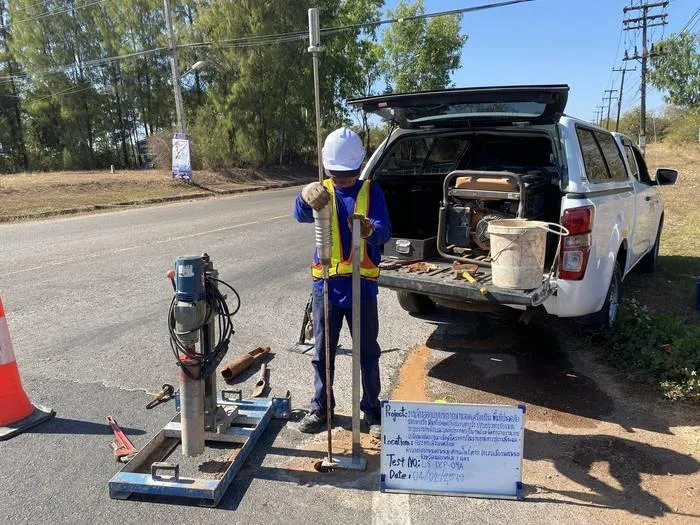
An 8 kg hammer falls freely 575 mm to drive a 60° cone into the soil; the penetration per blow (mm/blow) is measured and converted to an in-situ CBR — a tool designed specifically for pavement works. Read the full details in What Is the DCP Test?
- ✓ Light and portable; one or two people can run the test
- ✓ Gives field CBR immediately; used for compaction quality control and finding soft spots
- ✗ Reaches only ~1 m (rods can be extended to about 2 m, but results start to lose accuracy)
2. KPT — Kunzelstab Penetration Test (Light Dynamic Probing)
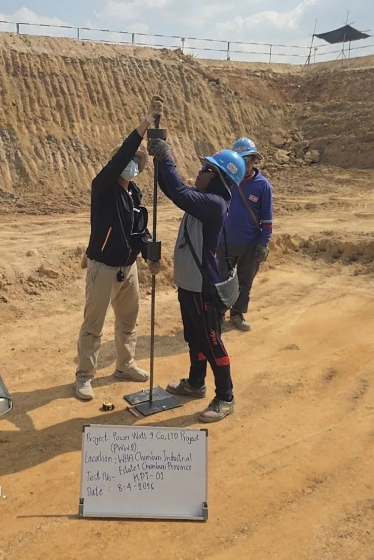
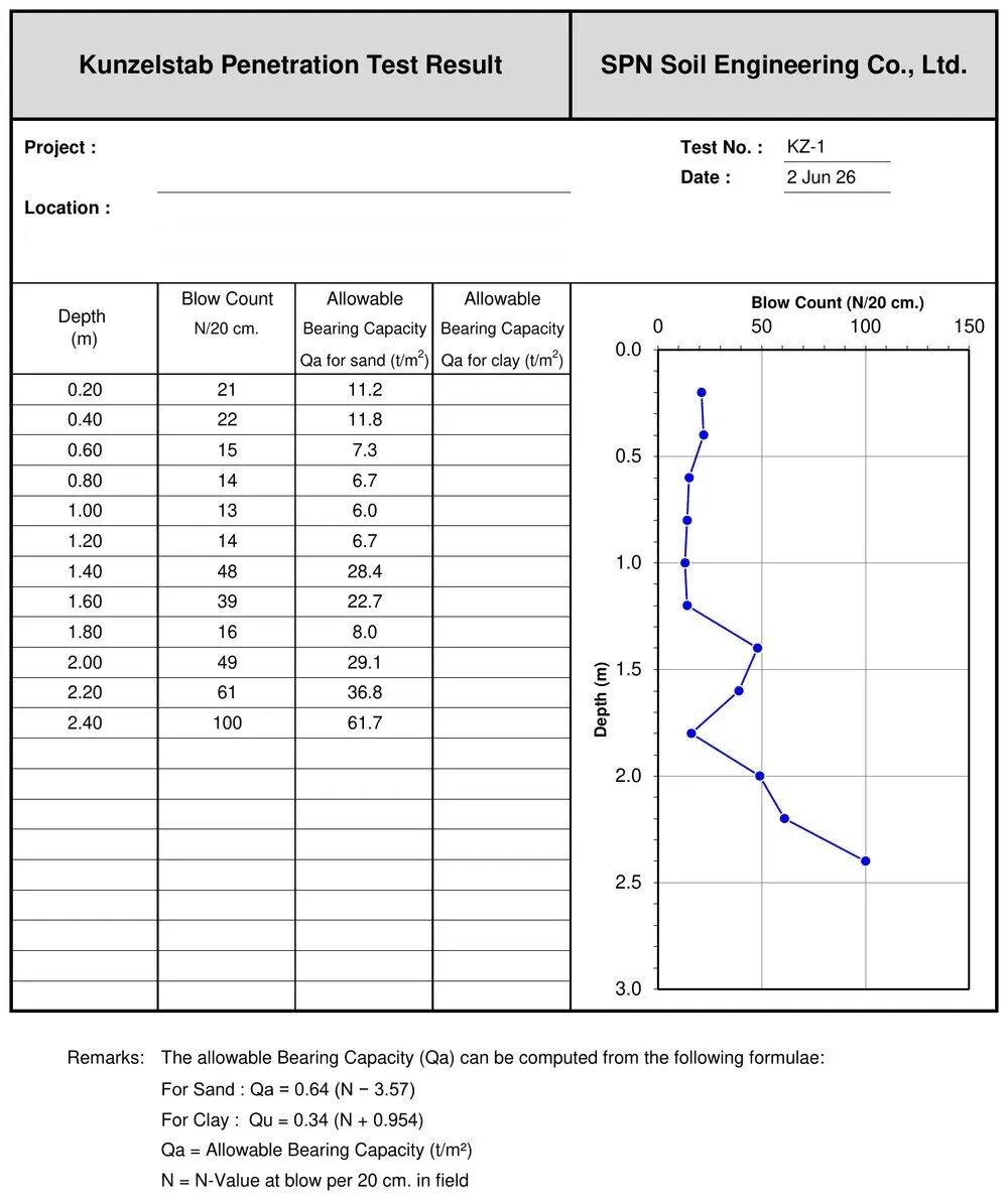
A 10 kg hammer falls 50 cm to drive a cone through the soil, and the number of blows per penetration (blows/20 cm) is counted. The cone is larger than the rod, which reduces rod friction — widely used in Thailand for shallow foundations of houses and small buildings. Read the full details in What Is the Kunzelstab Penetration Test (KPT)?
- ✓ Fast, economical, fits tight spaces, no drilling rig needed
- ✓ Estimates bearing capacity and the thickness of soft/stiff layers
- ✗ Reaches about 5 m (up to 7–10 m in soft soil, but with lower reliability)
- ✗ No soil sample is recovered — you only know the "resistance", not exactly what type of soil it is
3. SPT — Standard Penetration Test (ASTM D1586)
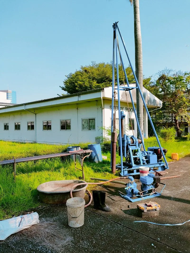
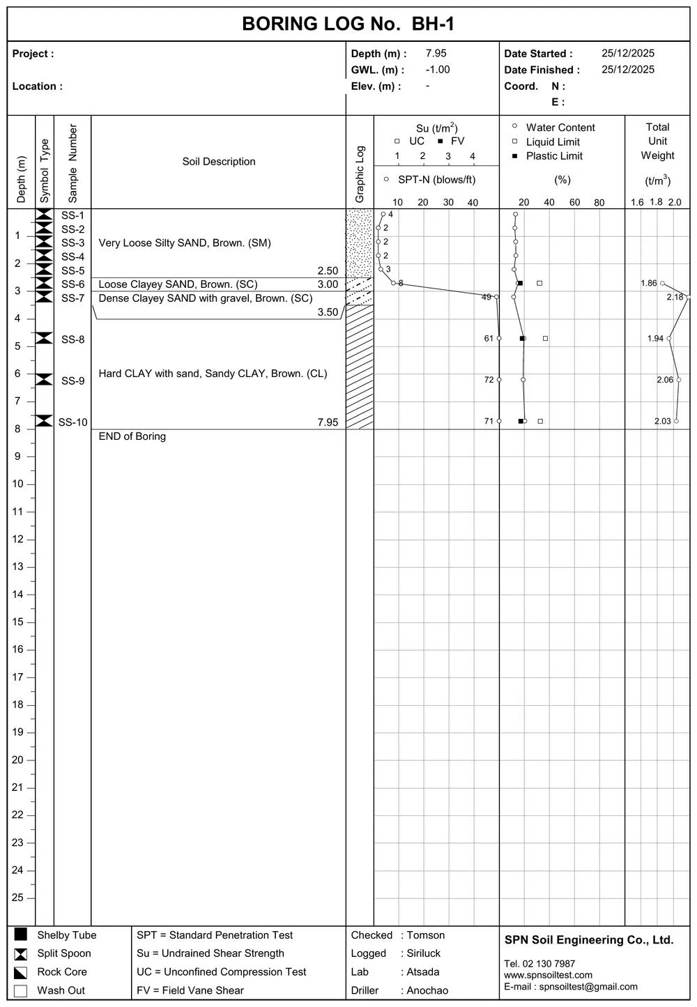
Performed in a borehole: a 63.5 kg hammer falls 76 cm to drive a split-spoon sampler 45 cm into the soil, and the blows over the last 30 cm give the N-value (SPT-N) — the main standard for foundation and pile design (see how to interpret it in SPT N-Value Interpretation)
- ✓ Reaches 10–30+ m, as deep as the borehole
- ✓ Recovers soil samples for classification and laboratory testing
- ✓ The N-value has the most complete set of correlations with design parameters (shear strength, density, pile capacity)
- ✗ Requires a drilling rig/boring set; the most expensive and time-consuming option
How Do DCP, KPT and SPT Differ?
← Scroll to see the full table →
| Topic | DCP | KPT | SPT |
|---|---|---|---|
| Reference standard | ASTM D6951/D6951M | Based on DIN 4094 (now DIN EN ISO 22476-2 · light DPL) | ASTM D1586 |
| Hammer mass / drop height | 8 kg / 575 mm | 10 kg / 50 cm | 63.5 kg / 76 cm |
| Energy per blow (theoretical) | ≈ 45 J | ≈ 49 J | ≈ 473 J |
| Measured value | DCP Index (mm/blow) | Blows/20 cm | SPT-N (blows/30 cm) |
| Practical depth | ~1 m | ~5 m | 10–30+ m |
| Used for | in-situ CBR | Approx. bearing capacity | N-value → foundation/pile design |
| Soil sample? | ✗ | ✗ | ✓ (Split Spoon) |
| Equipment | Portable, 1–2 people | Portable, 2–3 people | Drilling rig + crew |
| Speed | Fastest (a few minutes per point) | Fast | Slowest (1–2 days per borehole) |
| Relative cost | ฿ | ฿฿ | ฿฿฿฿ |
Energy per blow in the table is calculated from the hammer's potential energy m·g·h (e.g. SPT = 63.5 kg × 9.81 m/s² × 0.76 m ≈ 473 J) — SPT uses about 10 times more energy than DCP and KPT, so it can drive through stiff layers and reach much greater depths. The energy actually transferred to the rods is lower than the theoretical value and depends on the hammer type and operation.
The figure below summarizes the table above in a single section — all 3 methods use a drop hammer, but the hammer mass, drop height and achievable depth differ greatly.
Real Test Results from All 3 Methods
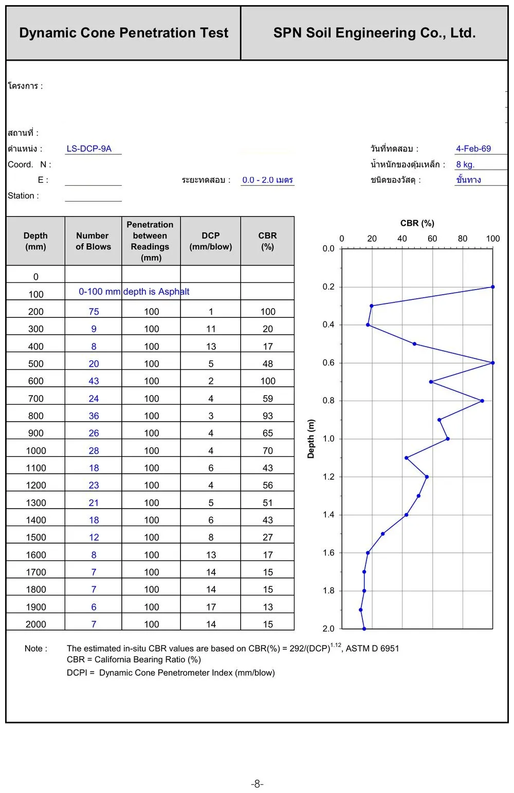
To show how the output of each method looks different, below are reports from real SPN projects — note that DCP gives the DCP Index/CBR, KPT gives blows/20 cm with an approximate bearing capacity, while SPT gives the N-value alongside a soil description from actual soil samples.
Which Method Suits Which Job?
← Scroll to see the full table →
| Type of work | Recommended method | Reason |
|---|---|---|
| Roads, parking areas, pavement layers, slab-on-grade | DCP | CBR of subgrade/subbase layers needed, no deeper than 1 m |
| Compaction quality control of fill, finding soft spots | DCP | Many points tested quickly to compare uniformity |
| Houses, 1–2 storey buildings, spread footings | KPT | Bearing capacity assessed to ~5 m is enough for shallow foundations; low cost |
| Preliminary check of soft layer thickness before committing to boreholes | KPT | Many probes spread across the site on a limited budget |
| Multi-storey buildings, factories, piled projects | SPT (soil boring) | Soil profile needed down to the pile bearing layer + samples for lab testing |
| Projects where the law/designer requires a boring log | SPT | KPT/DCP cannot replace a soil investigation report |
DCP = pavement (very shallow) | KPT = shallow foundations (medium) | SPT = deep foundations/piles (deep)
Can the 3 Methods Be Combined, and Why Is That More Cost-Effective?
On real projects the three methods do not compete — they complement each other:
- KPT probes spread across the site at many points on a modest budget → a rough map of soft layer thickness
- SPT borings at representative points chosen from the KPT results → N-values and soil samples for actual design
- DCP for acceptance of fill/pavement layers during construction → confirms that compaction achieved the specified strength
This approach covers the whole site without drilling an SPT borehole at every point, saving a lot of the investigation budget (see budget guidance in Soil Boring Prices 2026)
The model below shows where each of the 3 methods sits on the same project and which soil layers each one reaches — KPT spread across the site, SPT only at representative points but down to the sand layer, and DCP only in the pavement layers of roads and parking areas.
What to Watch Out for When Interpreting Results
DCP Index, KPT-N and SPT-N are different quantities with very different driving energies. Correlations between them exist in research, but they depend on soil type and location — interpretation should be left to a geotechnical engineer.
Groundwater level strongly affects foundation design; if you need to know it, you need a soil investigation
With a soft clay layer ~12–15 m thick, light probing can only say "soft all the way down", but pile design requires knowing the sand bearing layer, which is deeper than KPT can reach — such projects require soil boring + SPT only (read more in Bangkok Soft Clay and Foundations)
This article is provided as engineering knowledge. The choice of test method, number of points and interpretation of results should follow the project requirements and the judgment of a licensed engineer.