This article is a field guide, not theory. To understand what the test measures and how it is calculated, read What Is a Plate Bearing Test? Principles and Calculation. To find out which projects are legally required to perform it, read When Is a Plate Bearing Test Legally Required? The 200 kPa Criterion
How Do You Prepare a Site for a Plate Bearing Test?
Site preparation responsibilities are split fairly clearly between the contractor and the test team. The contractor handles earthworks, machinery and site access, while the test team handles the measuring instruments and load control. The table below is a checklist both sides can agree on before booking the test date.
← Scroll to see the full table →
| Item to prepare | Responsible party | Acceptance criteria |
|---|---|---|
| Excavate the test pit | Contractor | Down to the design foundation base level; pit bottom level and undisturbed |
| Reaction load | Contractor | Backhoe/excavator or kentledge providing reaction at least 1.2 times the maximum test load |
| Working area around the test point | Contractor | Clear a radius of about 3–4 m so the reference beams and supports can be set up without hitting the machine |
| Site access | Contractor | A pickup or small truck can reach the test point without getting bogged down or blocked by ditches |
| Drainage around the pit | Contractor | No standing water at the pit bottom; drainage channels or a tarpaulin cover when work stops |
| Test point layout and levels | Site supervisor / design engineer | Specify point coordinates, foundation base level and target stress (kPa) in advance |
| Test plate, jack, load cell, gauges | Test team | Calibrated, with certificates attached to the report |
| Load control and data recording | Test team | Carried out in accordance with DPT standard 1253-62 and ASTM D1195/D1196 |

The layout below combines every item in the table into a single drawing. Use it on site to agree where space must be left, how to position the excavator and where water must drain before the test date.
What Is the Reaction Load and How Large Must It Be?
The reaction load is the weight that resists the thrust of the hydraulic jack while it presses the test plate into the soil. The jack needs something to "push up" against before it can push down. If the reaction load is too small, the machine will be lifted off the ground before the soil reaches the target load, and the test will stop midway.
The approach is to calculate the required maximum test load first, then provide a reaction load at least 1.2 times that value.
Using a backhoe as the reaction load
In Thailand, the most common method is to have a backhoe or excavator already on site straddle the test point, with the jack placed under its belly. This is faster and cheaper than stacking kentledge, but three conditions must all be met.
- Position — the machine must straddle the test point so the jack sits under its center of gravity, not offset to either side; otherwise the machine will tilt or lift on one side
- Underbody clearance — there must be enough height to fit the test plate, jack, load cell and reference beams, while still leaving room for a person to read and adjust the gauges
- Load actually transferred to the jack — always less than the machine's own weight, because part of it still goes to the tracks; allow a margin above the figure calculated from machine weight alone
The table below gives the load required for each test plate size, so you can roughly judge whether the machinery on site is sufficient (assuming testing to 400 kPa, i.e. 2 times a design stress of 200 kPa).
← Scroll to see the full table →
| Plate size | Area | Load at 200 kPa | Load at 400 kPa | Min. reaction load (1.2×) |
|---|---|---|---|---|
| Ø 300 mm | 0.071 m² | 14.1 kN ≈ 1.4 t | 28.3 kN ≈ 2.9 t | ≈ 3.5 t |
| Ø 450 mm | 0.159 m² | 31.8 kN ≈ 3.2 t | 63.6 kN ≈ 6.5 t | ≈ 7.8 t |
| Ø 600 mm | 0.283 m² | 56.5 kN ≈ 5.8 t | 113 kN ≈ 11.5 t | ≈ 13.8 t |
| Ø 750 mm | 0.442 m² | 88.4 kN ≈ 9.0 t | 177 kN ≈ 18.0 t | ≈ 21.6 t |
Note: The figures above are preliminary estimates for equipment planning only. The actual target stress, plate size and test termination criteria must be set by the design engineer and the engineer supervising the test.
The larger the plate, the more reaction load is needed — and it rises steeply: from Ø 300 mm, where a small backhoe is enough, to Ø 750 mm, which needs a medium-to-large excavator. Plate size therefore has to be agreed at the planning stage, not decided on site.

Kentledge and ground anchors
When there is no sufficiently large machine on site, or the test point cannot be reached by vehicle, the options are:
- Kentledge — concrete blocks, steel plates or sandbags stacked on a steel frame spanning the test point. The advantage is a precisely controlled load; the drawbacks are the time needed to transport and stack it and the large footprint required
- Ground anchors (Anchor / Reaction Pile) — the reaction beam is tied to anchors or piles installed around the test point. Suitable for very high test loads or confined sites, but must be designed and installed in advance
The reaction system is the highest-risk part of the test. Kentledge stacks must be stable and must not topple, supports must stand on ground that can carry the load, and nobody may stand beneath the load while it is being applied. If the machine starts to tilt or lift, stop and release the pressure immediately.

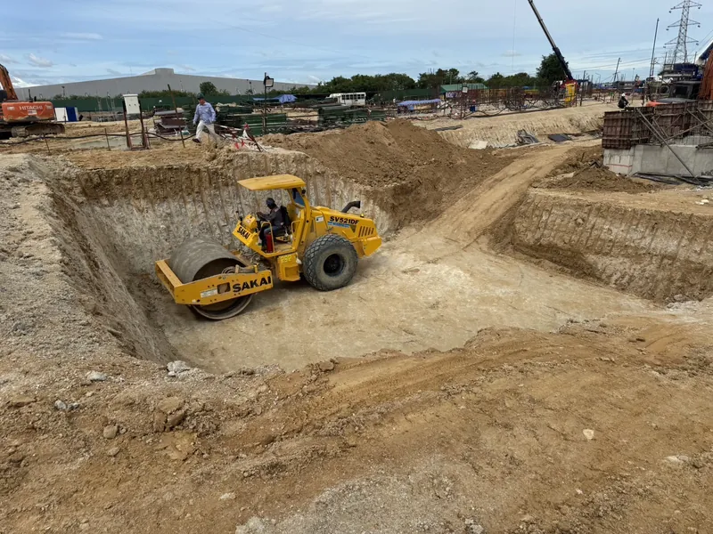
Excavating the Test Pit Correctly — How Deep and How Wide?
The most common site mistake is testing at the wrong level. The result then reflects a different soil layer from the one the foundation will actually bear on, and cannot be used to verify the design at all.
- Level — excavate down to the design foundation base level; do not test on the original ground surface, temporary fill, or fill not yet compacted to specification
- Pit width — typically open the pit to at least 4 times the test plate size, so the pit walls do not confine soil movement, which would make the result higher than reality
- Pit bottom surface — level and smooth it. If the surface is rough, spread a thin layer of fine sand to level only the plate seating area — do not place thick sand, or you end up testing the sand
- Timing — excavate as close to the test date as possible. A pit bottom left open for several days will dry and crack, or become saturated when it rains; either way the results are distorted
Before the scheduled date, compare the actual site with the drawing below. If the pit still lacks any of these seven items, fix it before calling in the test team.

How Far Away Must the Reference Beams and Gauges Be?
The reference beam is the beam used as a fixed datum for measuring plate settlement. There is only one principle: the beam supports must be outside the zone where the soil moves. If the supports sink along with the plate, the settlement readings will be smaller than reality and the whole curve will be wrong.
- Support distance — typically at least about 2.5 times the plate radius, or at least 2.4 m, whichever is greater, from the plate edge and from the reaction supports
- Number of gauges — install 2–4 settlement gauges (dial gauges or LVDTs) around the plate and average the readings to cancel out errors from plate tilt
- Resolution — gauges should read to 0.01 mm, because the reference settlement for determining the k value is only 1.25 mm
- Shading — cover the reference beams with an umbrella or tarpaulin throughout the test. Steel in direct sun expands and makes the readings drift continuously even though the soil has not settled further

Load measurement is just as important. Sites that read only the jack's pressure gauge are prone to errors from friction inside the cylinder. Using a load cell between the jack and the plate, read through a digital readout, gives the actual load transferred to the soil, traceable to the calibration certificate.


Weather and Timing — How Should You Plan the Test Day?
A Plate Bearing Test is carried out outdoors in an open pit, so rain directly affects the result. Water ponding at the pit bottom saturates the soil and temporarily reduces its bearing capacity, so the measured value will not represent the foundation's actual service condition.
- Prepare drainage channels around the pit and cover it with a tarpaulin when work stops
- If water ponds at the pit bottom, pump it out and let the soil recover, or postpone the test — never test over water
- Setting up and testing one point typically takes about half a day to one day, depending on how difficult the reaction load is to set up and the number of load increments
- The engineer-certified report is typically completed within 7–14 working days after fieldwork ends
Which Site Mistakes Make Test Results Unusable? (7 Mistakes)
These mistakes come up again and again, and almost all of them can be prevented before the test team arrives on site.
- Testing at the wrong level — not excavating to foundation base level, or testing on fill not yet compacted to specification; the result belongs to a different soil layer
- Uneven pit bottom — the plate does not seat fully and only touches at certain points; the plate tilts and the early part of the curve is distorted
- Insufficient reaction load — the machine is lifted before the target load is reached; the test must be terminated midway and repeated
- Reference beam supports too close — the supports are within the moving soil zone or close to the reaction supports, so measured settlement is less than the actual value
- Reference beams not shaded — the steel expands from heat and readings keep drifting even after the soil has stopped settling
- Water in the pit — the soil is saturated and temporarily weaker, giving results lower than reality
- Reading load from the pressure gauge only — with no load cell to cross-check, the actual load applied to the soil may differ from what is recorded
When a test result is unusable, the cost is not just a second round of testing. It also includes foundation work stopped while waiting for results, remobilizing the machinery and time lost along the construction schedule. Spending an extra half day on site preparation is always worth it.
What Information Should You Send the Test Team in Advance?
Information sent in advance lets the test team choose the plate size and reaction system and prepare the right equipment from the start, reducing the chance of having to go back for more equipment.
- Test point layout with coordinates, and the number of points required
- Design foundation base level (referenced to the project's construction datum)
- Target stress to be verified (kPa) and test termination criteria per the project specification
- Boring log or the project's soil investigation report, if available
- Type and size of machinery available on site, to assess whether it can serve as the reaction load
- Project safety requirements, such as site induction training or permit-to-work documents
If there is no subsoil information for the site at all, consider soil investigation as well, because a Plate Bearing Test only checks the shallow soil beneath the plate. If a weak layer is hidden deeper down, the results will look better than they really are — this is explained in the article Soil bearing capacity
What Should You Prepare Before Test Day, in Order?
Here is everything in this article arranged as a three-stage work sequence that site supervisors can easily follow.
- When booking the test date — send the test point layout, foundation base level, target stress (kPa) and the type of machinery on site to the test team, so they can choose the plate size and a reaction system providing at least 1.2 times the maximum test load
- Before test day (as close to it as possible) — excavate the pit to foundation base level, level the surface, dig drainage channels and prepare a tarpaulin cover, clear an area of about 3–4 m around the point, and check that a pickup can reach the test point
- Morning of the test — pump out any ponded water, check that the pit bottom is neither dry and cracked nor saturated, move the reaction machine into position with the jack under its center of gravity, then let the test team set up the reference beams outside the zone of influence with shading
Summary
Plate Bearing Test site preparation comes down to four main points: excavate the pit to the actual foundation base level and level the surface, provide a reaction load at least 1.2 times the maximum test load, leave room to set the reference beams outside the zone of influence and keep them shaded, and send the point layout, levels and target stress to the test team in advance
All of this takes only a few days of advance planning, yet removes almost all of the risk of unusable test results. For the legal requirements on whether your project must perform a Plate Bearing Test, see the article The 200 kPa criterion under the foundation Ministerial Regulation, and for an overview of foundation requirements, see Summary of the Foundation Ministerial Regulation B.E. 2566 (2023)
This article is provided as engineering knowledge. The distances, reaction loads and criteria are preliminary guidance for site planning. Selection of plate size, target stress and interpretation of results for design should be at the discretion of a licensed engineer and in accordance with DPT 1253-62 and the relevant ASTM standards.