What does a failed field density test mean?
A test fails when the percent compaction (%Compaction) — the dry density measured in the field compared with the maximum dry density from the laboratory — is below the criterion stated in the project specifications.
A common criterion for general compacted fill is at least 95% of Standard Proctor (ASTM D698), while pavement layers are usually specified higher and may reference Modified Proctor (ASTM D1557). The correct figure must always come from the project specifications, not from numbers passed along by word of mouth. For full test procedures and calculation formulas, see the article What is a Field Density Test? Test method and acceptance criteria
What is often overlooked is that a failing number only tells you that “something is wrong” — it does not tell you whether the problem lies in the compaction work or in the test. Tracing the cause to the right place therefore saves both time and rework costs.
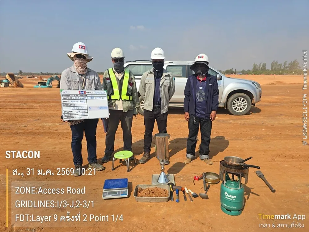
Why does %Compaction fail? 8 common causes
From actual field testing, the causes of failing results usually fall into these 8 groups: the first groups relate to the compaction work itself, and the last relates to the test.
1. Soil moisture outside the suitable range
Each soil compacts to its highest density at a particular moisture content, called the optimum moisture content (OMC). If the soil is too dry, friction between the particles prevents them from sliding together; if it is too wet, water fills the voids and carries the compaction force instead of the particles. Either way, the density achieved is low. General work typically controls moisture within about OMC ±2%, but the acceptable range must follow the project specifications.

2. Lifts too thick for the equipment
Roller energy reaches only a limited depth. If loose soil is placed too thick, the upper part becomes dense but the lower part of the lift stays loose, so a test over the full lift depth fails. Loose lift thicknesses in common use are about 15–30 cm, depending on the material type and roller size, and must comply with the project specifications.
The first two causes are the most common and often occur together. The figure below shows how moisture outside the control range and an over-thick lift can push %Compaction below the criterion, together with the order of checks before deciding on rework.
First compare the moisture content (w) at the failing point with OMC — if w is outside the control range, correct the moisture before re-rolling. If w is within range but %Compaction is still low, the problem usually lies in lift thickness, number of passes or roller type (items 2–4). If almost every point across the area fails even though moisture and rolling are normal, suspect the reference Proctor value first (item 5).
3. Too few roller passes, or rolling too fast
Too few passes is the easiest cause to fix. Sometimes the roller travels too fast, reducing the number of vibrations per unit distance, or the passes do not overlap enough, leaving strips that have not been compacted.
4. Wrong roller type for the material
Fine-grained soils such as clay need the shearing and kneading action of a sheepsfoot (padfoot) roller, while sand and gravel need vibration from a vibratory smooth drum roller. With the wrong type, adding more passes does not raise the density.
5. Fill material does not match the Proctor sample
The ρd,max value used as the divisor comes from one particular soil sample. If the borrow pit changes or material from several sources is mixed, the reference value will not match the soil actually compacted, and results may fail even though the compaction itself is fine.
6. Weak subgrade or pumping
If the underlying subgrade is weak or saturated, the soil surface visibly heaves up and down in waves as the roller passes. The energy that should compact the fill is lost in movement of the lower layer. In this case, no amount of re-rolling will raise the result.
7. Rain, ponding and poor drainage
Where the area is not graded to shed water, rain ponds in the placed lift and raises the moisture above the compactable range. This is common in fill work during the rainy season and often develops into the pumping described in item 6.
8. Errors in the test itself
Before concluding that the compaction has failed, rule out causes in the test itself, such as uncalibrated standard sand, a collapsing hole wall giving the wrong volume, incomplete recovery of excavated soil, a base plate not seated flat on the surface, or oversize particles that require correction per ASTM D4718.

What should you check before ordering rework?
Rework is costly in both time and equipment. Good practice is to work through these 6 checks before deciding.
- Is the right Proctor being used? — Standard Proctor (ASTM D698) and Modified Proctor (ASTM D1557) give clearly different ρd,max values; picking the wrong set skews the results immediately
- Does the reference value still match the actual material? — if the site soil has changed from the original sample, run a new Proctor on the material now in use
- When was the standard sand last calibrated? — the sand cone method per ASTM D1556 requires a calibrated sand density and cone correction
- Has the nuclear gauge done its standard count? — the ASTM D6938 method requires a daily standard count, and moisture readings should be checked periodically against oven-dried samples
- Are oversize particles present? — if a significant proportion is retained on the coarse sieve, correct the values per ASTM D4718 before comparing with the criterion
- Are the test points representative of the area? — edges, building corners, around pipes and along retaining walls are places the roller cannot reach and fail more often than the middle of the area
A common case is a failing result caused by comparison with the Proctor value of soil from a different source. When a new Proctor is run on the actual material and the results recalculated, they pass without any rework at all. Checking upstream should therefore always come before ordering fixes.
What symptoms point to which on-site fix?
← Scroll to see the full table →
| Cause | Symptoms observed on site | Remedy |
|---|---|---|
| Soil too dry | Dusty, grains do not bind, rough surface after rolling | Spray water evenly and mix by disc/plow for uniform moisture; let it distribute before re-rolling |
| Soil too wet | Soil sticks to the drum, wavy surface, deep wheel ruts | Turn the soil to dry it (aeration), blend in drier material, or wait for moisture to drop before rolling |
| Lift too thick | Top surface dense but full-depth test fails | Reduce loose lift thickness and recompact to the thickness specified |
| Too few passes | %Compaction consistently just below the criterion | Add passes, reduce travel speed, increase overlap between roller lanes |
| Wrong roller type | More passes do not raise the value | Switch to a roller suited to the material, e.g. sheepsfoot for clay, vibratory smooth drum for sand/gravel |
| Proctor does not match material | Whole area fails although compaction looks normal | Sample the actual material, run a new Proctor, and recalculate |
| Weak subgrade / pumping | Surface moves in waves as equipment passes | Stop compacting, drain the area, and have the engineer consider removing and replacing material or improving the subgrade |
| Testing error | Values jump between adjacent points | Check sand calibration, hole condition, soil recovery and oversize correction, then retest |
How do a test strip and rolling pattern help solve the problem?
A test strip is a small trial compaction area built before production work, to find out what lift thickness, roller type and number of passes this material needs to reach the required density. The result is called the rolling pattern, which becomes the working standard for the whole project.
In short, place soil at the required thickness in a strip about 20–30 m long, then test the density after each set of passes, e.g. 4, 6 and 8 passes. Then select the fewest passes that still pass the criterion consistently. This reduces both unnecessary over-rolling and repeated test failures.
The model below shows a test strip divided into 3 sections by number of roller passes, with density tested in every section, and how the results are read to select the rolling pattern for production work across the project.
When should you undercut instead of re-rolling?
Re-rolling works when the material is still sound and the problem is energy or moisture, but in some situations re-rolling does not help and removal should be considered.
- Soil saturated to the point of continuous pumping; the surface still moves after rolling
- Moisture too high to correct within the work schedule, especially clay in the rainy season
- Material containing organic matter, wood debris, construction waste, or soil that does not meet the fill material requirements
- A subgrade weaker than designed, which must be assessed as subgrade improvement work, not ordinary compaction
Choosing the remedy, such as replacing the fill, adding reinforcement, or stabilizing the soil with admixtures, is a design decision that must go through the project's responsible engineer and should not be based on a single test result.
How should you retest so the results can be relied on?
- Finish fixing the root cause first, then schedule the test — do not simply retest straight away without fixing anything
- Choose new points; do not retest in the old hole, where the soil is already disturbed, and backfill the old hole with well-compacted material
- Record the compacted lift, location and coordinates of every point for traceability
- If a point fails again, extend testing around it to see whether the problem is local or covers the whole area
- Keep both the failing and passing results in the report, as evidence that the work has been corrected and verified
What should you check before calling for testing?
- Proctor results are available for the actual material, of the same type as referenced in the specification
- Loose lift thickness is as specified and placed evenly across the area
- Moisture is within the acceptable range, checked before compaction starts, not after rolling is finished
- The roller type suits the material and follows the rolling pattern from the test strip
- Compaction covers edges, corners and around pipes, using small equipment where large rollers cannot reach
- The surface is graded to drain, and the area is covered when rain is likely
- Schedule the test only when the work is truly ready, giving the compacted lift and number of points required in advance
Where the bearing capacity of the compacted layer must be confirmed, testing often continues with a Plate Bearing Test, or the uniformity of pavement layers is assessed with a DCP Test alongside the density results. See the full range of services on the soil testing page, and earthwork planning guidance in Planning site grading and earthworks
Summary
When a field density test fails, do not order rework right away. Check three levels in order: first the accuracy of the reference values and the test, then the compaction variables such as moisture, lift thickness and number of passes, and finally the condition of the underlying subgrade. Fixing the actual cause is always faster and cheaper than trial-and-error re-rolling.
The cost of field density testing depends on the number of points, the test method and the supporting laboratory tests required. For a free quotation within 24 hours, call 064-746-9601 or LINE @spnth. Prices exclude travel and equipment mobilization, which are charged extra according to the distance to site.
This article is general guidance for analyzing compaction problems, not design advice for any specific project. Acceptance criteria, lift thickness and appropriate remedies must follow the project specifications and the judgment of the project's licensed engineer.